Preliminary procedure, Operator’s manual, Table 2: list of required equipment – Teledyne LeCroy HFP2500 User Manual
Page 29
Operator’s Manual
922253-00 Rev A
23
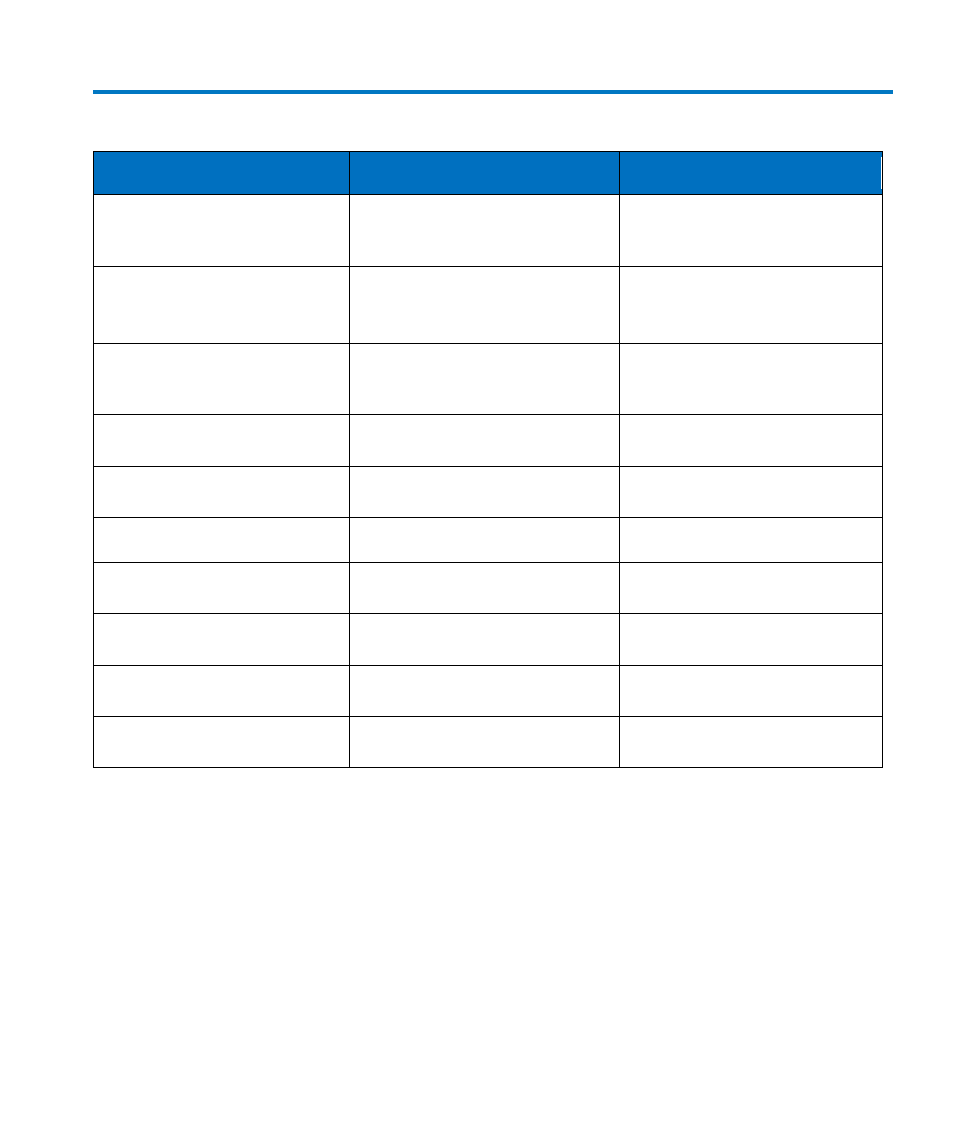
Table 2: List of Required Equipment
Description
Minimum Requirements
Example Test Equipment
Digital Oscilloscope
ProBus interface
Teledyne LeCroy WavePro960
Teledyne LeCroy LT344
Digital Multimeter (DMM) with
test probe leads
4.5 digit
DC: 0.1% Accuracy
AC: 0.1% Accuracy
Agilent Technologies 34401A
Fluke 8842A-09
Function Generator
Sine Wave output amplitude
adjustable to 14.14 Vp-p (5 Vrms)
into 1 MΩ at 70 Hz
Agilent Technologies 33120A
Stanford Research Model DS340
Power Supply
0-12 V, settable to 10 mV
HP E3611A
BNC Coaxial Cable (2 ea.)
Male to Male, 50 Ω, 36" Cable
Pomona 2249-C-36
Pomona 5697-36
BNC Tee Connector
Male to Dual Female
Pomona 3285
Calibration Fixture
ProBus Extender Cable
Teledyne LeCroy PROBUS-CF01
Terminator, Precision, BNC
50 Ω ± 0.05%
Teledyne LeCroy TERM-CF01
Banana Plug Adapter
(2 ea.)
Female BNC to Dual Banana Plug
Pomona 1269
BNC to Mini-grabber
BNC Male to Mini-grabber Cable,
36"
Pomona 5187-C-36
Preliminary Procedure
1. Connect the HFP2500 probe to the female end of the ProBus Extension Cable. Connect the
male end of the ProBus Extension Cable to channel 1 of the oscilloscope.
2. Turn the oscilloscope on and allow at least 30 minutes warm-up time for theHFP2500 and
test equipment before performing the Verification Procedure.
3. Turn on the other test equipment and allow these to warm up for the time recommended
by the manufacturer.
4. While the instruments are reaching operating temperature, make a photocopy of the
Performance Verification Test Record (located in Appendix A), and fill in the necessary data.