Wiring is power limited, Figure 3: horn operation – System Sensor SYNC-1 User Manual
Page 2
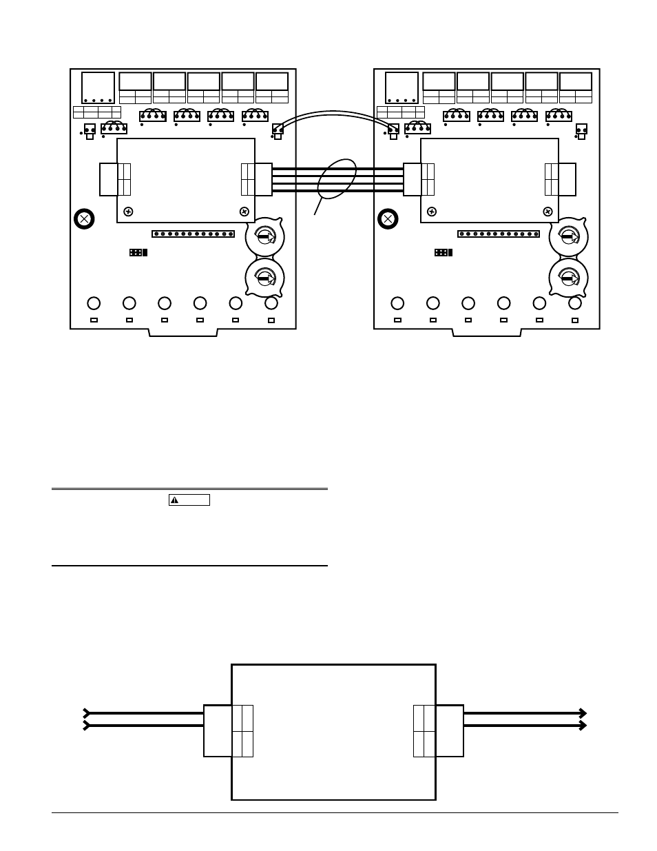
To interconnect SYNC-1 Accessory Cards wire the Slave and Horn connections
as shown in Figure 2. The slave wires will synchronize all NACs correspond-
ing to the interconnected boards. Any SYNC-1 which has no connections to its
slave in terminals will operate as a master. It will generate a signal which will
be duplicated by all interconnected units downstream. The horn wires will en-
able horn control on all NACs corresponding to the interconnected boards.
Horn control also requires a silenceable NAC circuits to be wired to the horn
in terminals of the master SYNC-1 Accessory Card as shown in Figure 3.
A maximum of 11 Slaves Sync-1 Cards can be connected to a Master Sync-1
Card, totalling 12.
CAUTION
All horn and slave wiring interconnecting SYNC-1 accessory cards must be
contained within the same enclosure. If multiple enclosures are used they
must be located within 20 feet of each other with all horn and slave wiring be-
tween enclosures routed inside of conduit. This conduit should be grounded
metal containing no other field wiring.
SLA
VE IN
HORN IN
—
+
—
+
SLA
VE OUT
HORN OUT
—
+
—
+
Silenceable NAC Output
Wiring is
Power Limited
To Next SYNC-1 Horn In
C0122-01
FIgURE 3: HORN OpERATION
BASE
ADDRESS
NAC
PS
NAC
PS
— +
+ —
NAC
PS
— +
+ —
NAC
PS
— +
+ —
NAC
TOP
BOT
– +
+ NAC –
– +
– PS +
SLC
PS
— +
+ —
+1
+2
+3
+4
+5
T11
T10
T0
+0
T12
T1
T2
T3
T4
T5
T13
T14
T15
T16
ENABLE POWER SUPPLY MONITOR
— +
+ —
0
1 2
3 4 5
6
7
8
9
0
1 2
3 4 5
6
7
8
9
SLA
VE I
N
HORN IN
—
+
—
+
SLA
VE OUT
HORN OUT
—
+
—
+
BASE
ADDRESS
NAC
PS
NAC
PS
— +
+ —
NAC
PS
— +
+ —
NAC
PS
— +
+ —
NAC
TOP
BOT
– +
+ NAC –
– +
– PS +
SLC
PS
— +
+ —
+1
+2
+3
+4
+5
T11
T10
T0
+0
T12
T1
T2
T3
T4
T5
T13
T14
T15
T16
ENABLE POWER SUPPLY MONITOR
— +
+ —
A/B SELECT
DISABLE 1
DISABLE 2
DISABLE 3
0
1 2
3 4 5
6
7
8
9
0
1 2
3 4 5
6
7
8
9
SLA
VE IN
HORN IN
—
+
—
+
SLA
VE OUT
HORN OUT
—
+
—
+
DISABLE SHORT CIRCUIT PROTECTION
ENABLE POWER SUPPLY MONITOR
A/B SELECT
DISABLE 1
DISABLE 2
DISABLE 3
DISABLE SHORT CIRCUIT PROTECTION
ENABLE POWER SUPPLY MONITOR
Wiring is
Power Limited
C0123-01
FIgURE 2: CONNECTINg TWO SYNC-1 CARDS (CLASS B OpERATION, ONE pOWER SUppLY USED)
D500-51-00
2
I56-2190-005