System Sensor MB500 User Manual
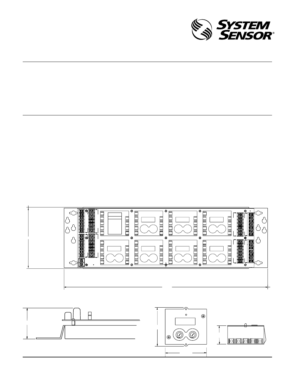
Mb500 module panel, Installation and maintenance instructions, Figure 1a. mb500 module panel
D500-35-00
1
I56-917-02
MB500 Module Panel
INSTALLATION AND MAINTENANCE INSTRUCTIONS
A Division of Pittway
3825 Ohio Avenue, St. Charles, Illinois 60174
1-800-SENSOR2, FAX: 630-377-6495
NOTICE: This manual should be left with the owner/user
of this equipment.
General Description
Before installing this module panel, please thoroughly read
the system wiring and installation manuals. Also be aware
of the appropriate local and national standards and codes
of practice for the placement and installation of control
panels.
The MB500 Module Panel is for use with any listed enclo-
sure suitable for fire-protection signaling applications. It
Specifications
PANEL (Figures 1A and 1B)
MODULE (sold separately; Figure 1C)
Depth:
2.17 inches (5.51 cm)
Depth:
1.50 inches (3.81 cm)
Height:
6.13 inches (15.57 cm)
Height:
2.70 inches (6.86 cm)
Width:
20.18 inches (51.26 cm)
Width:
2.82 inches (7.16 cm)
Operating Temperature Range:
32
°
to 120
°
F (0
°
to 49
°
C)
Operating Humidity Range:
10% to 93% relative humidity, noncondensing
Construction of Bracket:
16-gauge galvanized steel
provides a platform for the installation of up to 8 (two rows
of 4) standard monitor and/or control modules. Wiring and
mounting requirements of the modules are reduced by us-
ing the MB500.
The MB500 will support any combination of monitor and
control modules on one panel, but a combination of power-
limited and nonpower-limited modules is NOT permitted.
The monitor and control modules used with the MB500
meet the same electrical specifications as the individual
M500MB, M500CH, and M502M.
2.17
0 9
1
2
4
3
7
8
1
2
5
6
3
0 9
8
7
5
4
6
2.7
2.82
9
8
7
6
5
1.50
Figure 1B. MB500 module panel height:
Figure 1C. Module dimensions:
A78-2622-00
A78-2623-00
+2
+2
7
5
0 9
6
1
2
4
3
7
8
1
2
5
6
3
4
0 9
3
8
7
5
4
6
8
9
-1
-1
+2
+2
7
5
0 9
6
1
2
4
3
7
8
1
2
5
6
3
4
0 9
3
8
7
5
4
6
8
9
-1
-1
+2
+2
7
5
0 9
6
1
2
4
3
7
8
1
2
5
6
3
4
0 9
3
8
7
5
4
6
8
9
-1
-1
+2
+2
7
5
0 9
6
1
2
4
3
7
8
1
2
5
6
3
4
0 9
3
8
7
5
4
6
8
9
-1
-1
4
2 COMM +
2 COMM +
1 COMM -
1 COMM -
3
E
3
F
4
4
7
5
6
8
9
3
5
6
7
9
8
+2
+2
7
5
0 9
6
1
2
4
3
7
8
1
2
5
6
3
4
0 9
3
8
7
5
4
6
8
9
-1
-1
+2
+2
7
5
6
4
3
8
9
-1
-1
7
L
E
U
D
L
E
5
U
6
D
O
M
O
M
8
9
B
A
3
4
E
L
U
E
5
L
6
U
E
9
M
D
O
M
D
O
7
8
F
G
B
C
U
+2
+2
7
5
0 9
6
1
2
4
3
7
8
1
2
5
6
3
4
0 9
3
8
7
5
4
6
8
9
-1
-1
4
3
E
G
5
L
6
H
4
3
E
L
U
5
6
+2
+2
7
5
0 9
6
1
2
4
3
7
8
1
2
5
6
3
4
0 9
3
8
7
5
4
6
8
9
-1
-1
3
H
D
O
7
M 8
9
E
C
4
5
L
U
6
D
O
7
D
9
M 8
M
3
9
D
O
M
7
8
E
D
4
5
L
U
O
D
6
7
9
8
WARNING
DISCONNECT ALL POWER SOURCES
BEFORE SERVICING
C = CONTROL M = MONITOR
MODULE TYPE ADDRESS
A C M ______
B C M ______
C C M ______
D C M ______
E C M ______
F C M ______
G C M ______
H C M ______
ALL MODULES MUST BE USED FOR
EITHER POWER - LIMITED OR
NON - POWER LIMITED APPLICA-
TIONS. NO COMBINATION IS
ALLOWED.
A
B
C
D
E
F
G
H
6.13
20.18
Figure 1A. MB500 module panel:
A78-2621-00