Figure 2. bb-2 cabinet, Installation steps, Figure 3. typical mounting hole locations – System Sensor IM-10 User Manual
Page 2: Figure 4. mounting the ch-6 chassis, None one two three
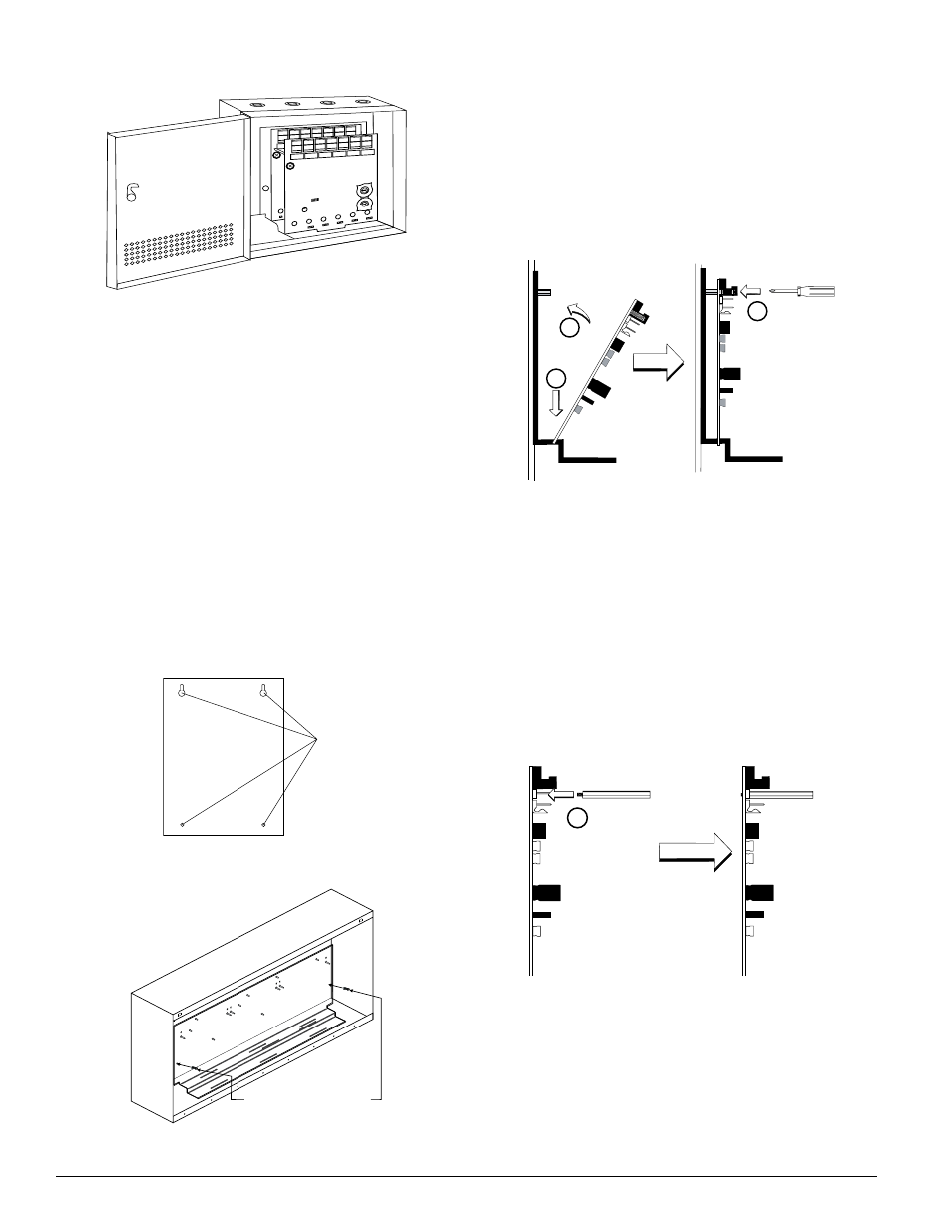
3. Module Installation
There are two methods for installing a module in the rear posi-
tion of a chassis. Method one is for installation of a rear mod-
ule only, when no module will be installed in front of it. Refer
to Figure 5 for instructions. Method two is for installation of
a rear module when another module will be installed in the
chassis position in front of it. Refer to Figures 6a and 6b for
method two. All necessary screws and standoffs are supplied
with the modules.
Figure 5. Installation of rear module only, method one:
2
3
1
Step 1: Insert the bottom of the IM-10 module down into a rear
slot on the chassis.
Step 2: Carefully swing the upper edge of the board back
towards the back of the chassis until it touches the
two standoffs.
Step 3: Align two 4-40 screws with the two standoffs and tighten.
Step 4: Address and wire the modules according to the instruc-
tions in this manual.
The steps in Figures 6a and 6b describe and illustrate module in-
stallation when the rear chassis position and the position in front
of it will be filled. Front position installation is possible only if the
rear position is filled with another module.
Figure 6a. Installation of IM-10 module in a rear
chassis position, method two:
1
Step 1: Insert the bottom edge of the IM-10 module down into a
rear slot of the chassis.
Step 2: Carefully swing the upper edge of the board towards the
back of the chassis until it touches the short standoff at-
tached to the chassis.
Step 3: Align the long standoff with the short standoff and tighten.
Figure 2. BB-2 Cabinet:
0
1
2 3 4 5 6
7
8
9
0
7
8
6
5
4
3
2
1
9
10
11
12
13
14
15
BASE
ADDRESS
ADDRESS
DISABLE
NONE
ONE
TWO
THREE
0
1
2 3 4 5 6
7
8
9
0
7
8
6
5
4
3
2
1
9
10
11
12
13
14
15
BASE
ADDRESS
ADDRESS
DISABLE
NONE
ONE
TWO
THREE
The front IM-10 module positions of each chassis are offset below
the rear IM-10 module positions so that all of the status indicators
are visible.
Cabinets
A BB-6 cabinet will house the CH-6 chassis with up to six IM-10
modules installed on it. Refer to cabinet installation documents
for dimensions.
The BB-2 cabinet houses one or two IM-10 modules on the inter-
nal chassis that is part of the cabinet. Refer to cabinet installation
documents for dimensions.
INSTALLATION STEPS
1. Cabinet Mounting
In a clean, dry area, mount the backbox using the four holes
provided in the back surface of the cabinet (Figure 3).
2. Chassis Installation
The CH-6 chassis is mounted in the BB-6 cabinet. It is shipped
with two self-threading screws, which are used to fasten the
chassis to the back wall of the cabinet (see Figure 4).
Figure 3. Typical mounting hole locations:
Backbox
Mounting
Holes
Figure 4. Mounting the CH-6 chassis:
Mount with self-threading screws
to back of cabinet
The BB-2 cabinet comes with the chassis already installed, so no
mounting is necessary.
D500-47-00
2
I56-1797-007
C0237-00
C0885-00
C0235-00
C0236-00
C0225-00