System Sensor ZCK-1 User Manual
Installation and maintenance instructions
D770-31-00
1
I56-1610-009R
ZCK-1, ZCK-1E, ZCK-1EG, ZCK-1EN and ZCK-50
Zonecheck Key Switch for Control and
Monitoring of the Zonecheck Flow Switch Tester
INSTALLATION AND MAINTENANCE INSTRUCTIONS
3825 Ohio Avenue, St. Charles, Illinois 60174
1-800-SENSOR2, FAX: 630-377-6495
www.systemsensor.com
ELECTRICAL SpECIFICATIONS
Operating Voltage:
ZCK-1: 120V, 60Hz; ZCK-1E, ZCK-1EG, ZCK-1EN and ZCK-50: 220VAC, 50Hz, 7.5W Max.
Operating Temperature:
0°C to 49°C (32°F to 120°F)
Operating Humidity:
5% to 95% RH (non-condensing)
Mounting Options:
Includes back box for surface or flush mounting.
For pre-wiring, use a 4
11
/
16
˝ x 4
11
/
16
˝ back box
Operation Modes:
Self Test: Wired locally. Timed out, pump disabled after 2min ±15sec
Group Test: Interconnected
LED Operation:
Ready state: No LED
Test initiation: Green LED
Flow switch activation:
Red LED (ZCK-1), Green LED (ZCK-1E, ZCK-1EG, ZCK-1EN and ZCK-50) Tested to EN 61010-1
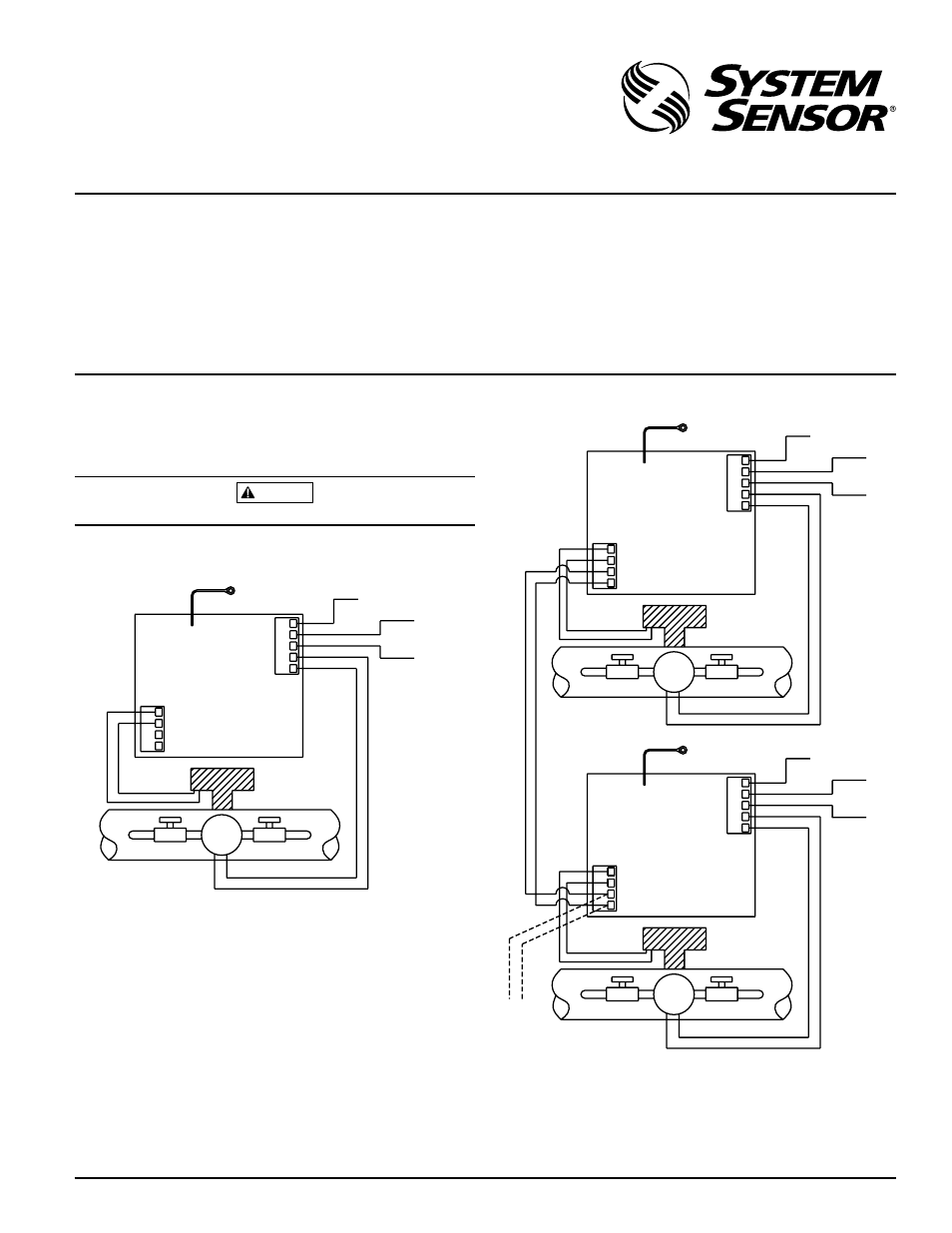
WIRING DIAGRAM FOR STAND ALONE APPLICATION
}
}
AC GROUND
AC POWER
GND
JUNCTION BOX
AC
PUMP
PUMP
AC
WF INPUT
WATERFLOW
DETECTOR
INTER-CONNECT
PUMP
TO EARTH GND.
OR ATTACH TO
FOR INTERCONNECTING MULTIPLE ZONECHECK UNITS
}
}
}
}
WATERFLOW
DETECTOR
JUNCTION BOX
OR ATTACH TO
JUNCTION BOX
OR ATTACH TO
INTERCONNECT
SWITCH FOR
ZONECHECK
TO NEXT
AC GROUND
AC POWER
GND
AC
PUMP
PUMP
AC
TO EARTH GND.
PUMP
WF INPUT
INTER-CONNECT
PUMP
AC POWER
AC GROUND
TO EARTH GND.
PUMP
PUMP
AC
AC
GND
INTER-CONNECT
WF INPUT
WATERFLOW
DETECTOR
NOTE: WF INPUT not required for key switch operation if waterflow detec-
tor is connected to a panel or other monitoring device. AC power and pump
wiring must conform to NEC or your local codes.
ZCK-1E, ZCK-1EG, ZCK-1EN AND ZCK-50
If the pump used in this application is grounded, it must share the same in-
put/output earth ground as the device.
An overcurrent protection device such as a switch or circuit breaker is re-
quired. The protection device must be clearly marked and have a maximum
rating of 16 A.
There are no ventilation requirements.
pRE-OpERATION GUIDELINES
Contact central monitoring station or appropriate fire safety personnel prior
to testing Zonecheck.
WARNING
If this product is not used as specified, it may become impaired.
W0158-00
W0158-00
I56-16
10-009R
FIGURE 1: WIRING DIAGRAM FOR STAND ALONE AppLICATION
FIGURE 2: FOR INTERCONNECTING MULTIpLE ZONEChECK UNITS
Note: Zonecheck key switch features a time out function in Self Test mode that
allows the user to start the flow switch test which will end automatically after
two minutes. The waterflow detector will be activated during the 2 minute
timeframe, upon activation the waterflow detection LED on the zonecheck
key switch will turn on and remain that way until the key is returned to the
standby position.