System Sensor WFD European Models User Manual
Page 2
D770-53-00
2 I56-2617-004R
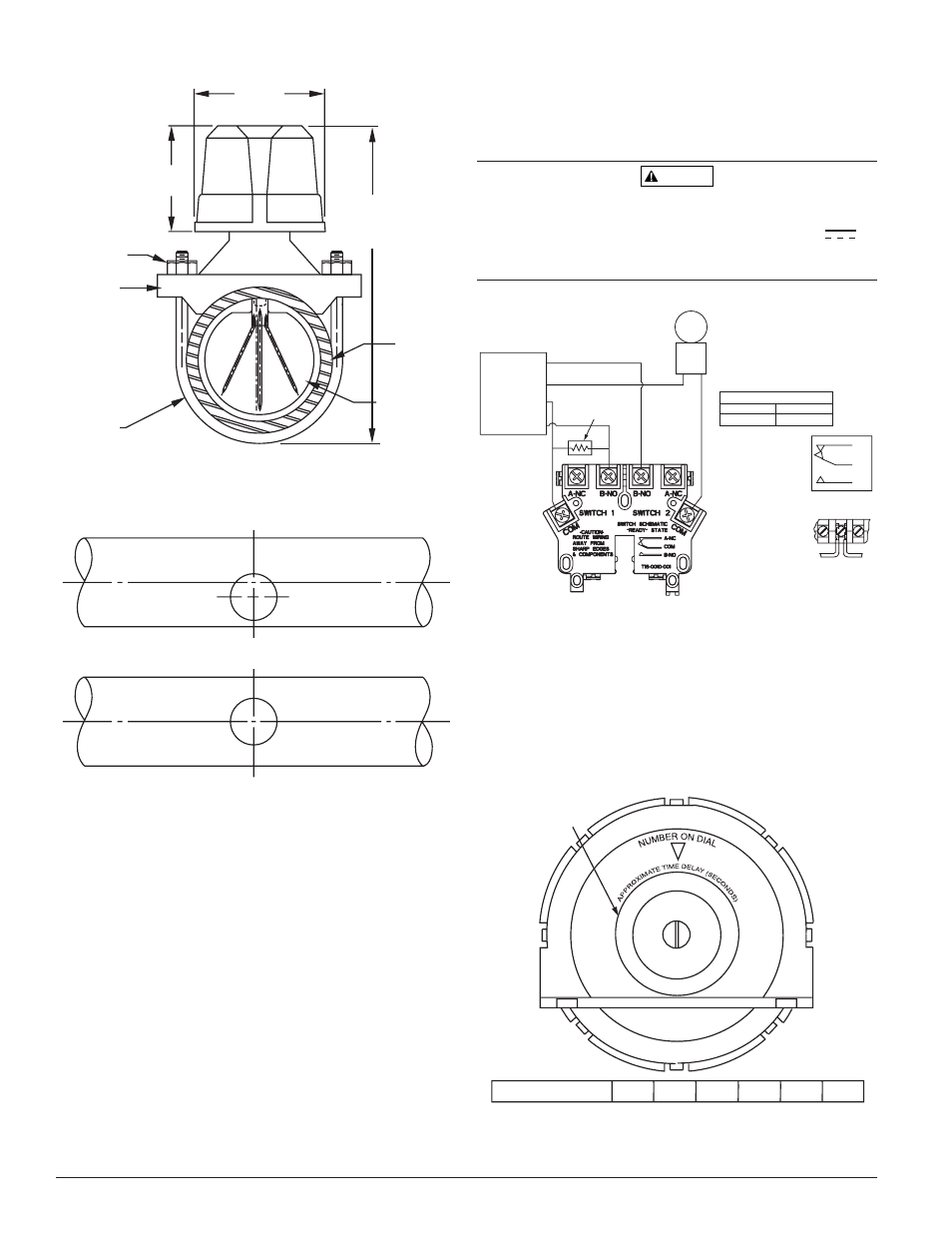
FIGURE 1. MOUNTING DIMENSIONS:
7.6 CM
(3˝)
9.5 CM
(3
3
/
4
˝)
PIPE DIAMETER
PLUS 13.3 CM
(5
1
/
4
˝)
PIPE
VANE
PIPE
U-BOLT
NUT
PIPE
SADDLE
U-BOLT
OVERALL WIDTH = PIPE DIAMETER + 7.6 CM (3˝)
W0105-00
FIGURE 2. LOCATION OF MOUNTING HOLE:
WRONG
RIGHT
REMOVE BURRS FROM EDGE OF HOLE. CLEAN OUT SCALE
AND FOREIGN MATTER FROM INSIDE WALL OF PIPE.
W0106-00
PREOPERATION TESTING
1. Fill the sprinkler system and check for leaks around the WFDE. If it
leaks, first check for proper torque on U-bolt nuts. If leak persists, drain
the system and remove the detector (see removal instructions under
Maintenance). Check for dirt or foreign objects under the gasket. Check
that pipe surface is not dented. Reinstall the detector and check again for
leaks. Do not proceed until all leaks have been stopped.
2. Connect an ohmmeter or continuity tester across (COM and B-NO) termi-
nal switch contacts (see Figure 3). The ohmmeter should show an open
circuit, no continuity.
3. Deflect the actuator lever and hold it until the pneumatic delay shaft
releases the switch buttons. The ohmmeter or continuity tester should
show a short circuit after the delay has elapsed. If there is no delay,
check the setting of the delay adjustment dial.
FIELD WIRING
1. All models have two SPDT switches. Switch contacts (COM and B-NO) are
closed when water is flowing and open when water is not flowing. Con-
nect the switches as shown in Figure 3 depending on the application.
2. When connected to a listed sprinkler/fire alarm control panel, the initiat-
ing circuit must be non-silenceable.
3. A ground screw is provided with all WFDE units. When grounding is re-
quired, clamp wire with screw in hole located between conduit entrance
holes, see Figure 6.
4. Use proper waterproof conduit fittings where required.
5. A 22.2 mm conduit hole is provided for electrical connection. An additional
22.2 mm diameter knockout is provided for multiple line connections.
WARNING
High Voltage. Electrocution Hazard. Do not handle live AC wiring or work on a de-
vice to which AC power is applied. Doing so may result in severe injury or death.
When utilizing switches at voltages greater than 74VDC
or
49VAC
~
means to provide all–pole disconnection must be incorporated in
the field wiring, such as a circuit breaker.
FIGURE 3. FIELD WIRING:
+
+
–
–
SSM24-X
SSV120-X
NOTE: COMMON AND B-NO
CONNECTIONS WILL CLOSE
WHEN VANE IS DEFLECTED, I.E.,
WHEN WATER IS FLOWING. DUAL
SWITCHES PERMIT
APPLICATIONS TO BE COMBINED
ON A SINGLE DETECTOR.
BREAK WIRE AS
SHOWN FOR
SUPERVISION OF
CONNECTION. DO
NOT ALLOW
STRIPPED WIRE
LEADS TO EXTEND
BEYOND SWITCH
HOUSING. DO NOT
LOOP WIRES.
POWER
24VDC OR
120VAC
INITIATING
LOOP
UL-LISTED
COMPATIBLE
CONTROL PANEL
CONTACT RATINGS
125/250 VAC
24 VDC
10 AMPS
2.5 AMPS
SCHEMATIC OF
INDIVIDUAL
SWITCH IN
“NO WATERFLOW”
CONDITION
SUGGESTED EOL
RESISTOR
B-NO
COM
A-NC
W0356-01
MECHANICAL DELAY ADJUSTMENT
The pneumatic delay is preset at dial setting 25 at the factory. To adjust the
delay, turn the adjustment dial on the delay mechanism. Turn clockwise to
increase the delay, counterclockwise to decrease the delay. Delay can be ad-
justed over a range from 0 to 30 seconds maximum, see Figure 4.
NOTE: Set the delay to the minimum required to prevent false alarms due to
flow surges.
After extended service, parts of the detector may become worn reducing the
delay time and causing false alarms. If this happens, increase the delay.
FIGURE 4. DELAY ADJUSTMENT DIAL:
20
0
5
10
15
25
DIAL SETTING
0
5
10
15
20
25
DIAL SETTING EQUALS DELAY IN SECONDS REFERENCE ONLY.
DELAY
ADJUSTMENT
DIAL
W0102-04