System Sensor PIBV2 User Manual
Page 2
N770-03-00
3
I56-0394-010R
SECTION 4
REVERSINg ThE ACTION OF PIBV2
1. Loosen the three
3
/
16
˝ hex (socket head) screws on the top of the black
switch enclosure so that the switch enclosure is loose and free to move
(see Figure 5).
2. Slide the switch enclosure away from the conduit entry toward the actu-
ating pivot arm as far as possible and tighten the 3 screws to secure the
enclosure. (Ensure that switch enclosure remains oriented away from the
conduit entry as screws are tightened.)
3. Grasp the spring at the center and lift it over the actuating cam so that it
seats on the opposite side of the actuator (see Figure 5).
NOTE: Lever actuator may need to be adjusted to allow spring to be moved.
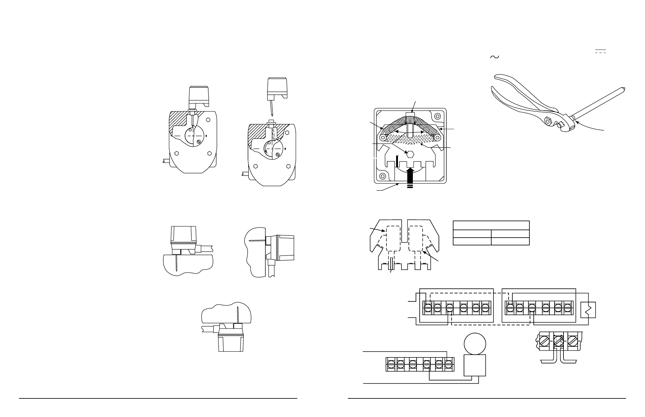
FIgURE 5:
CONDUIT
ENTRY
SOCKET
HEAD
SCREW
SPRING
IN FINAL
POSITION
ACTUATING LEVER
SWITCH
ENCLOSURE
SPRING
IN INITIAL
POSITION
SLIDE IN
THIS DIRECTION
W0225-00
WARNING: High Voltage. Electrocution Hazard. Do not handle live AC wiring
or work on a device to which AC power is applied. Doing so may result in
severe injury or death.
When utilizing switches at voltages greater than 74 VDC
or 49 VAC
, means to provide all-pole disocnnection must be incorporated in the
field wiring, such as a circuit breaker.
FIgURE 7: ACTUATINg ARM BREAkAwAy FEATURE:
BREAK
HERE
W0321-00
N770-03-00
2
I56-0394-010R
4. (a) In a falling flag installation (flag lowers as valve is closed), measure
the distance from the bottom of the head to the upper surface of the
target that will contact the actuating lever of the PIBV2. Add
3
⁄
32
˝ to this
measurement and mark the outside of the housing at that location. Drill
with a
23
⁄
32
˝ drill bit and tap a
1
⁄
2
˝ NPT thread.
(b) In a rising flag installation (flag rises as valve is closed), measure the
distance from the bottom of the head to the lower surface of the target
that will contact the actuating lever. Subtract
3
⁄
32
˝ to this measurement
and mark the outside of the housing at that location. Drill with a
23
⁄
32
˝
drill bit and tap a
1
⁄
2
˝ NPT thread.
5. Replace the head and target assembly.
6. Loosen the set screw that holds the nipple on the PIBV2 and remove
the nipple.
7. Screw the locknut onto the threaded nipple which is supplied with the PIBV2.
8. Screw the nipple hand tight into the
1
⁄
2
˝ hole in the valve and tighten the
locknut against the housing to secure the nipple in position.
9. Insert a probe into the hole through the nipple to measure the distance
from the open end of the nipple to the desired position on the target as-
sembly. Subtract
5
⁄
8
˝ from the distance and set the length of the actuating
lever of the PIBV2 from the end of the enclosure to this distance. Tighten
the screw which holds the actuating lever.
NOTE: Place cover over PIBV2 to ensure that actuating lever does not
interfere with cover. If actuating lever interferes with cover, remove
lever and break off additional length at breakaway point. Repeat step
8 to re-install actuator lever. Refer to Figure 7.
10. Close the valve 3 to 4 revolutions.
11. Install the PIBV2 onto the nipple and orient the conduit entry down (See
Figure 4). Apply pressure to the PIBV2 and lock the set screws to secure
the nipple to the PIBV2.
12. Slowly open the valve to its fully open position. The switch should trip
as the valve opens, but not force the actuating lever against the nipple
when fully open. To check for this condition, open the valve fully and
depress the top of the actuating cam to stretch the actuating spring fur-
ther. There should be some additional movement available. If no move-
ment is available, damage may occur to the PIBV2 actuator lever. It will
be necessary to adjust the flag location by removing the head and turn-
ing the handle while the valve stem is disengaged (refer to the valve
manufacturer.)
13. After checking the fully open position to ensure adequate clearance,
close the valve slowly until the PIBV2 contacts trip. The switches must
trip within
1
⁄
5
of the full travel distance of the valve.
14. If the PIBV2 does not change states within
1
⁄
5
of the length of travel, it
may be necessary to adjust the flag up or down by removing the head
and turning the handle (refer to the valve manufacturer.)
SECTION 2
INSTALLATION INSTRUCTIONS FOR BUTTERFLy VALVES (SEE FIgURE 3)
1. Remove the
1
⁄
2
˝ NPT plug from the valve housing.
2. Loosen the set screw that holds the nipple on the PIBV2 and remove
the nipple.
3. Screw the locknut onto the threaded nipple which is supplied with the
PIBV2.
4. Screw the nipple into the
1
⁄
2
˝ NPT hole and hand tighten. Tighten the
locknut firmly to the housing to secure the nipple.
5. Open the valve fully and close the valve approximately 3 revolutions,
noting which direction the target moves.
6. Retract the actuating arm and install PIBV2 onto the nipple, orienting the
PIBV2 to trip the switch as the valve closes. If the conduit entry is on the
wrong side, it will be necessary to reverse the action of the switch (see
Section 4). Apply pressure to PIBV2 and tighten set screw to secure the
assembly.
7. Slide the actuating arm into the valve until it bottoms on the flag, but do
not tighten the screw which holds the actuating lever.
NOTE: Place cover over PIBV2 to ensure that actuating lever does not
interfere with cover. If actuating lever interferes with cover, remove lever
and break off additional length at breakaway point. Refer to Figure 7.
8. Open the valve to the full open position and tighten screw to hold actuat-
ing arm in position. (Actuating arm length will adjust slightly as valve is
opened.) Check to ensure that in the full open position the actuating arm
is not resting on the nipple. Do this by depressing the actuating cam to
further stretch the spring, ensuring that more travel is available when the
valve is open. If there is no travel, damage may occur to PIBV2 actuating
arm. Some slight alteration of the valve stop setting may be necessary to
ensure that no damage occurs.
9. Carefully close valve and note the number of handle revolutions until the
switch trips. The switch must trip within 1⁄5 of the total travel range of
the valve.
FIgURE 3:
TO
O
P
E
N
CLOSE
CLOSE
W0214-00
SECTION 3
gENERAL INSTALLATION INSTRUCTIONS
1. Installation Positions
FIgURE 4:
ACTUATOR VERTICAL (DOWN)
ACTUATOR HORIZONTAL
ACTUATOR VERTICAL (POINTING UP)
EXAMPLES OF ACCEPTABLE MOUNTING POSITIONS:
EXAMPLE OF MOUNTING POSITIONS
NOT ACCEPTABLE:
W0381-00
2. Ground Screw — A ground screw is provided with all supervisory switch
models. When grounding is required, clamp wire with the screw in hole
located near conduit entrance.
3. Wiring — See Figure 6, Page 4.
FIgURE 6:
TOP VIEW
SWITCH 1
CO
M
CO
M
A
B
B
A
SWITCH 2
CONTACT RATINGS
125/250 VAC
24 VDC
10 AMPS
2.5 AMPS
SUP. SWITCH
B
B
COM
COM
SUP. SWITCH
B
B
COM
COM
TYPICAL FACP CONNECTION
TO NONSILENCEABLE
INITIATING ZONE
OF LISTED FACP
END-OF-LINE
RESISTOR
B
COM
TO POWER
SOURCE
COMPATIBLE
WITH BELL
LOCAL
BELL
TYPICAL LOCAL BELL CONNECTION
BREAK WIRE AS SHOWN FOR SUPERVISION
OF CONNECTION. DO NOT ALLOW STRIPPED
WIRE LEADS TO EXTEND BEYOND SWITCH
HOUSING. DO NOT LOOP WIRES.
STRIP GAUGE
NOTE: COMMON AND B CONNECTIONS
WILL CLOSE WHEN VALVE MOVES
1
/
5
OF
ITS TOTAL TRAVEL DISTANCE.
W0223-00