Figure 3. typical piping diagram for eps120exp, Figure 4. switch location, Figure 2. typical piping diagram for eps40exp – System Sensor EPS40EXP and EPS120EXP User Manual
Page 2: Warning
BREAK WIRE AS SHOWN FOR
SUPERVISION OF CONNECTION.
DO NOT ALLOW STRIPPED WIRE
LEADS TO EXTEND BEYOND
SWITCH HOUSING. DO NOT
LOOP WIRES.
A78-2346-02
D770-26-00
2
I56-1428-001R
Installation
1. Back out cover tamper set screw and remove cover (Fig. 1).
2. Mounting the Switch
The device is designed to be mounted in the upright posi-
tion; side mounting is also acceptable. Locate it where
vibration, shock, and mechanical loading are minimal.
Refer to piping diagram above (Figures 2 and 3).
a. Mount the device directly to the line via the 1/2″ NPT
pressure connection. The use of teflon pipe sealant
tape is recommended. Be sure the fitting is tight
enough to prevent leaks.
A78-2397-00
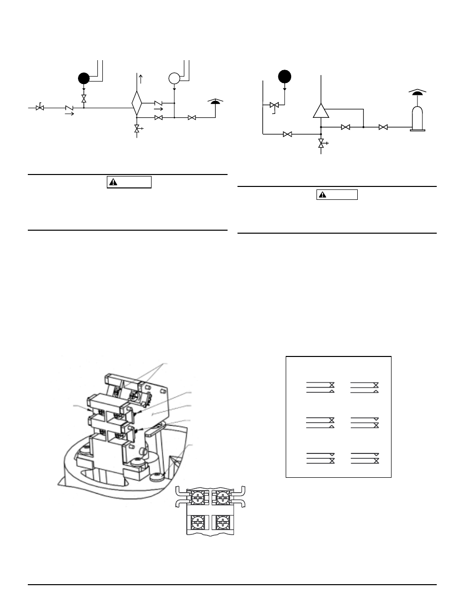
Figure 3. Typical piping diagram for EPS120EXP
DRY
PIPE
VALVE
OS & Y
VALVE
WATER
BY-PASS
TEST
VALVE
LOCAL ALARM
SHUT OFF
VALVE
WATER
MOTOR
GONG
CHECK
VALVE
EPS40EXP
CHECK
VALVE
AIR LINE
SHUT-OFF
VALVE
INSTALL
BLEEDER
VALVE FOR
TESTING
EPS10EXP
DRY SYSTEM
WIRE TO SUPERVISORY
CIRCUIT OF FIRE ALARM
CONTROL PANEL
WIRE TO ALARM
INDICATING CIRCUIT
OF FIRE ALARM
CONTROL PANEL
TO
SPRINKLER
SYSTEM
Table 1. Electrical connections (referenced at
factory settings):
b. Apply tightening torque to the brass hex portion of
the device.
High voltage. Electrocution hazard. Do not handle live AC
wiring or work on a device to which AC power is applied.
Doing so may result in severe injury or death.
3. Wire the device in accordance with the National
Electrical Code. Two 1/2″ NPT conduit entry holes have
been provided in the mounting base to accept explosion
proof conduit fittings. If necessary, remove conduit entry
plug with 3/8” square wrench.
4. Connect wiring to terminals (see Figure 4 and Table 1).
CAUTION
WET
SYSTEM
ALARM
CHECK
VALVE
OS & Y
VALVE
OS & Y
VALVE
WATER
BY-PASS
VALVE
AIR
PRESSURE
SUPPLY
BLEEDER
TEST
VALVE
EPS120EXP
LOCAL ALARM
SHUT OFF
VALVE
RETARD
WATER
MOTOR
GONG
A78-2398-02
COMMON
TERMINAL
SWITCH #2
(LOW SWITCH)
TERMINAL
“B”
GROUND
SCREW
Figure 4. Switch location:
WARNING
To prevent ignition of hazardous atmospheres, disconnect
circuits before removing cover. Keep cover closed while cir-
cuits are live. Conduit runs must have sealing fittings con-
nected within 18” of the enclosure.
SWITCH #1
(HIGH SWITCH)
Figure 2. Typical piping diagram for EPS40EXP
SW2
SW1
SWITCHES AT NORMAL SYSTEM PRESSURE
SWITCHES AT LOW TRIP POINT
SW1
SW2
MODELS EPS40EXP, EPS120EXP
SWITCHES AT HIGH TRIP POINT
SW1
SW2
B
COM
A
B
COM
A
B
COM
A
A
COM
B
A
COM
B
A
COM
B