Figure 3. wiring afd to bell – System Sensor AFDT and AFDTH User Manual
Page 3
D770-34-00
3
I56-1621-004R
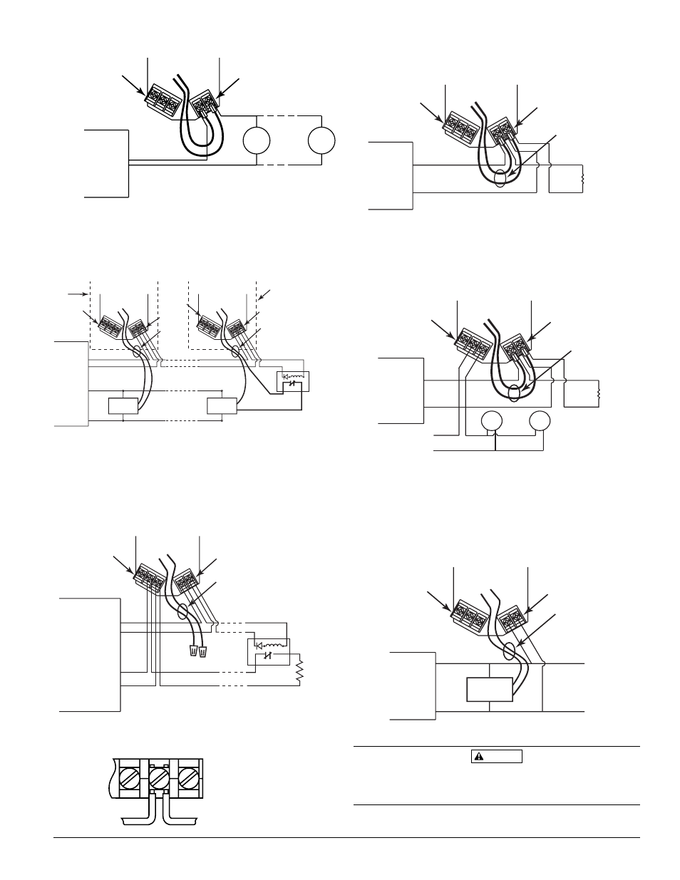
Figure 3. Wiring AFD to bell:
BELL
BELL
POWER SOURCE
A B CO
M
POWER
TERMINALS
AUX RELAY
TERMINALS
Figure 4. (4 Wire Addressable) Wiring the AFD to an
addressable panel using an auxiliary power supply for
power:
Remove the Relay Wires from under the Power Terminals.
Connect these wires to the Addressable Module.
Break wire as shown for
supervision of connection.
DO NOT allow stripped wire
leads to extend beyond
switch housing. Do NOT
loop wires.
Figure 7. Wiring the AFD to a panel and other device:
Leave the Relay Wires installed under the Power Terminals and
connect the panel initiating loop wires as shown below. The AFD
requires power to operate, therefore connect the FACP initiating
loop wires to the Power Terminals and Relay Wires as shown.
EOL
OR NEXT
DEVICE
FACP
POWER SOURCE
BELL
BELL
A B COM
POWER
TERMINALS
AUX RELAY
TERMINALS
RELAY
WIRES
Figure 6. Wiring the AFD to a panel:
Leave the Relay wires installed under the Power Terminals and
connect the panel initiating loop wires as shown below.
OR NEXT
DEVICE
POWER
TERMINALS
AUX RELAY
TERMINALS
A B
C
OM
EOL
FACP
RELAY
WIRES
TO NEXT MODULE
OR EOL
INTELLIGENT
MODULE
FACP
A B COM
POWER
TERMINALS
AUX RELAY
TERMINALS
RELAY
WIRES
Figure 8. (2 Wire Addressable) Wiring the AFD to an
addressable panel using the SLC loop wires for power:
Remove the Relay Wires from under the Power Terminals.
Connect these wires to the Addressable Module.
NOTE: Consult FACP Manufacturer’s Compatibility Guide prior
to installation.
Figure 5. Wiring the AFD using 4 wires. (Aux. Power from
Panel):
Remove the Relay Wires from the Power Terminals. Cut off the
spade lugs from the ends of the Relay Wires. Put wire nuts over
ends of Relay Wires as shown. Use Aux. Relay Terminals to make
connection to panel and next device as shown..
NOTE: To comply with NFPA code, never put more than two
wires in a wire nut.
Relay wires and power terminal wiring must be contained within
either a common enclosure or enclosures within 20 feet of each
other with wiring inside conduit.
CAUTION
AUX. POWER
OUTPUT
INITIATING
LOOP
A B COM
POWER
TERMINALS
AUX RELAY
TERMINALS
RELAY
WIRES
FACP
EOL POWER
SUPERVISION
RELAY (SHOWN
ENERGIZED)
A77-716 12/24V
EOL
AUX.
POWER
OUTPUT
MODULE
SLC
LOOP
A B COM
POWER
TERMINALS
AUX RELAY
TERMINALS
RELAY
WIRES
FACP
MODULE
A B COM
POWER
TERMINALS
AUX RELAY
TERMINALS
RELAY
WIRES
NOTE: PLACE MODULE EOL
RESISTOR ACROSS RELAY
WIRES INSIDE AFD COVER.
NOTE: PLACE MODULE EOL
RESISTOR ACROSS RELAY
WIRES INSIDE AFD COVER.
AFD
ENCLOSURE
AFD
ENCLOSURE
EOL POWER
SUPERVISION
RELAY (SHOWN
ENERGIZED)
A77-716 12/24V