System Sensor 546-9000 Cover Tamper Switch User Manual
9000 cover tamper switch
D770-33-00
1
I56-0052-000
546-9000 Cover Tamper Switch
INSTALLATION AND MAINTENANCE INSTRUCTIONS
A Division of Pittway
3825 Ohio Avenue, St. Charles, Illinois 60174
1-800-SENSOR2, FAX: 630-377-6495
www.systemsensor.com
NOTICE: This manual should be left with the owner/user
of this equipment.
General Information
The System Sensor 546-9000 cover tamper switch mounts
to AFD and LFD Series waterflow devices to monitor re-
moval of the cover. Cover removal produces a switch out-
put. The unit will reset when the product cover is
reinstalled.
Wiring Instructions
1. Remove the waterflow detector cover using the security
wrench provided.
2. Attach the cover tamper switch to upper PCB by snap-
ping. The cover tamper switch assembly snaps into the
bracket mounting holes on the upper PCB in the orienta-
tion shown in Figure 1.
Specifications
Contact Ratings:
5A @ 125/250 VAC
3A @ 30 VDC
Operating Temperature Range:
32
°
to 120
°
F (0
°
to 49
°
C)
Shipping Weight:
0.115 lbs.
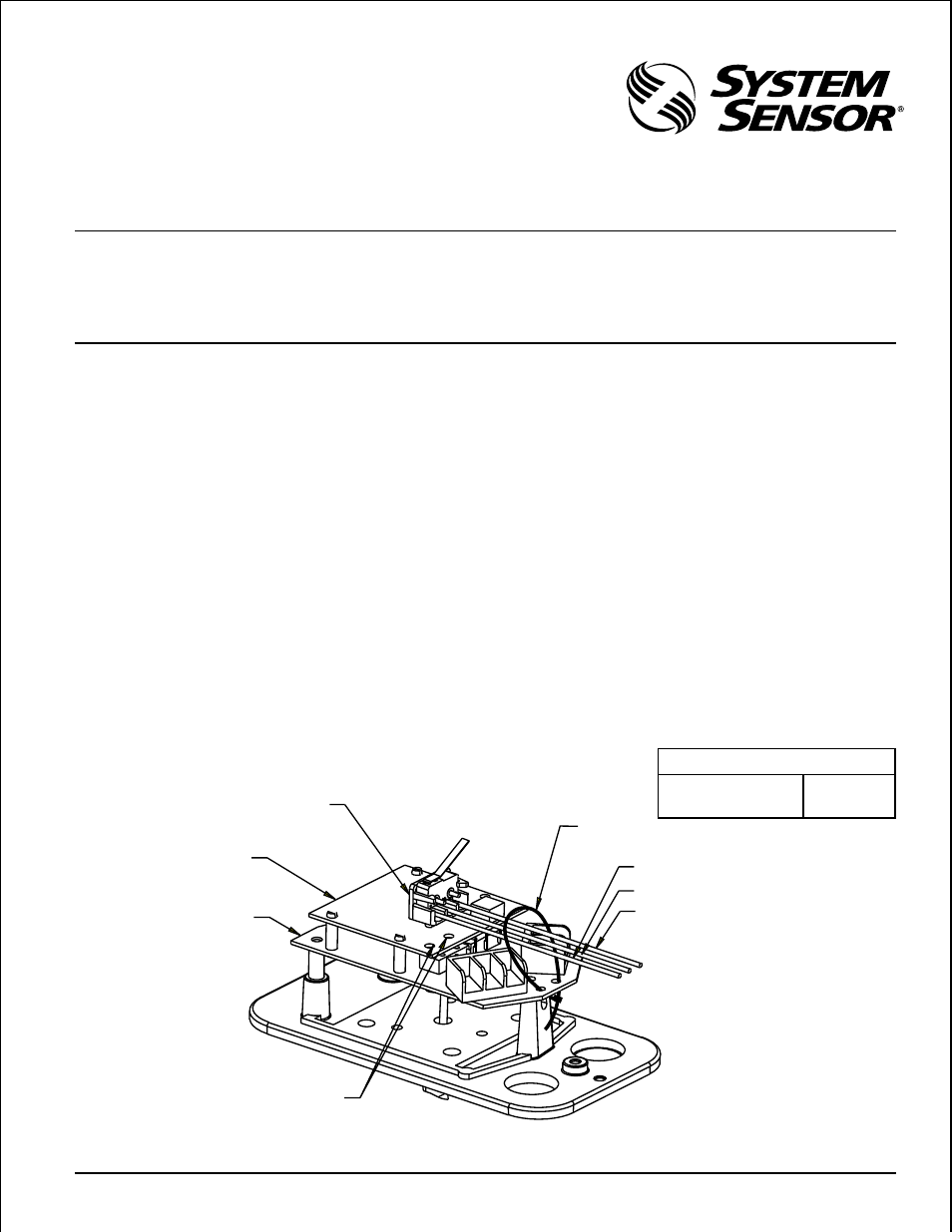
Figure 1.
For use with System Sensor Models:
AFD and LFD Series waterflow detectors
NOTE:
To avoid possible damage, support upper PCB
when installing cover tamper switch bracket as-
sembly.
3. Secure the three wires from cover tamper switch to lower
PCB using supplied tie wrap. See Figure 1.
4. Route wires away from mechanisms.
5. Wire the circuit as shown in Figures 2, 3, or 4, or as re-
quired by the installation requirements and as approved
by the authority having jurisdiction. Clip the unused
wire from the tamper switch and use the wire nut to pro-
tect from shorting.
6. Perform the required system tests and include the cover
tamper switch in the test by alternately replacing and re-
moving the cover to produce the desired circuit effects.
7. After testing, secure the cover with the security wrench.
A78-2630-00
COVER TAMPER SWITCH
BLACK/BLUE: OPEN
COVER OFF
BLACK/RED: CLOSED
COVER TAMPER SWITCH
BRACKET ASSEMBLY
P/N 546-9000
UPPER PCB
BRACKET MOUNTING HOLES
BLACK (COM)
BLUE (NORMALLY OPEN)
RED (NORMALLY CLOSED)
LOWER PCB
TIE WRAP