System Sensor 546-7000 Cover Tamper Switch User Manual
Cover tamper switch
D770-05-00
1
I56-403-03
Cover Tamper Switch
INSTALLATION AND MAINTENANCE INSTRUCTIONS
A Division of Pittway
3825 Ohio Avenue, St. Charles, Illinois 60174
1-800-SENSOR2, FAX: 630-377-6495
NOTICE: This manual should be left with the owner/user
of this equipment.
CAUTION
Do not leave unused wires exposed. Do not use in poten-
tially explosive atmospheres.
General Information
This cover tamper switch mounts to all System Sensor
WFD, WFDT, OSY2 and PIBV2 terminal block units. Cover
removal produces a switch output. The unit will reset when
the product cover is reinstalled.
Installation Guidelines
Before installing any cover tamper switch, be thoroughly
familiar with:
Specifications
Contact Ratings:
5.0A @ 125/250 VAC
2.5A @ 24 VDC
Overall Dimensions:
1
1
/
4
˝H x 2˝W x
3
/
4
˝D
Operating Temperature Range:
32
°
to 120
°
F (0
°
to 49
°
C)
Shipping Weight:
0.025 lb.
NFPA 72:
National Fire Alarm Code
NFPA 13:
Installation of Sprinkler Systems, specifically
section 3.17.
NFPA 25:
Inspection, Testing and Maintenance of Sprin-
kler Systems, specifically chapters 4 and 5.
Other applicable NFPA standards, local codes and the re-
quirements of the authority having jurisdiction.
Failure to follow these directions may result in failure of the
device to report an alarm or trouble condition. System Sen-
sor is not responsible for devices that have been improperly
installed, tested or maintained.
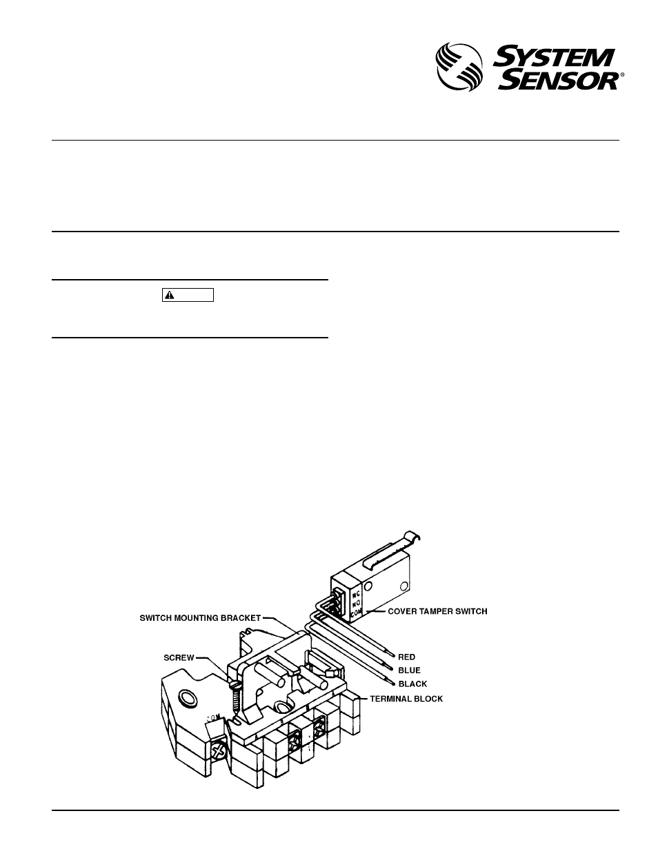
Mounting Instructions
1. Install switch mounting bracket onto terminal block us-
ing the 2 screws provided, shown in Figure 1.
2. Snap the switch onto the switch mounting bracket in po-
sition shown in Figure 1.
A78-1661-00
Figure 1. Assembly Diagram: