System Sensor SMB600 User Manual
Page 2
Surface Wiring Mounting Instructions
1. Read the installation instructions appropriate for the
detector head to be used and determine the number of
wires used.
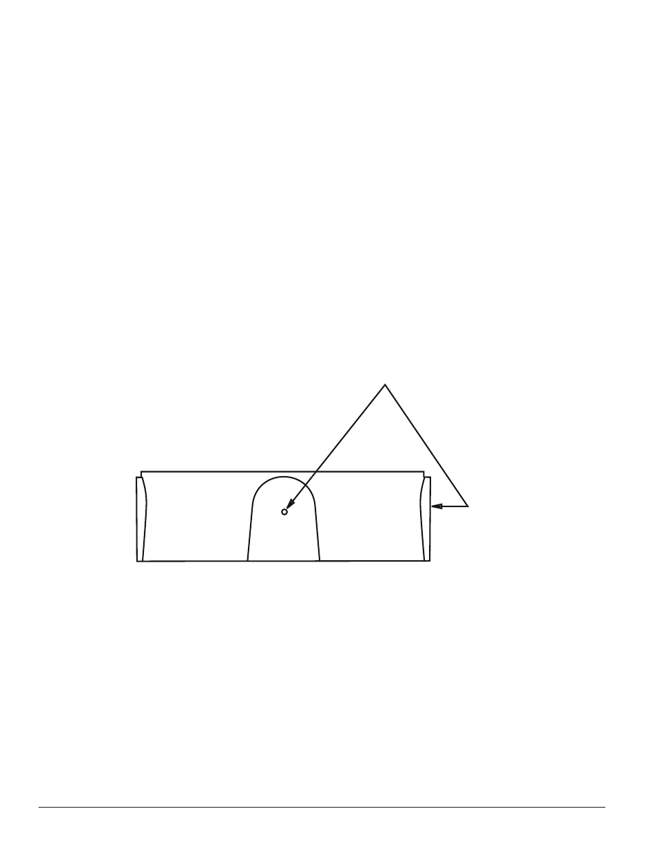
2. Drill out the appropriate holes using the drill centers
provided on the sides of the adaptor (see Figure 4).
Do not use conduit larger than 1/2″ to connect to the
SMB600.
3. Mount the adaptor on the ceiling using the 2 keyholes
and appropriate screws or bolts (not included). The
screws or bolts must be long enough to go through the
adaptor (5/32″ or 4mm) and still fasten securely to the
ceiling.
4. Pull wiring and conduit through the drilled hole(s). Attach
nut(s) (not included) to conduit fitting and tighten.
DRILL
CENTERS (4)
Figure 4. Drill centers:
C0525-00
5. Wire detector base using the instructions included with
the base.
6. Mount the base, using the supplied screws, in the
SMB600 Surface Mounting Adaptor Kit.
NOTE: When using the B402, B404, or B406 with the sur-
face mount base, the 4 alignment ribs (see Figure
1) must be cut off flush or below the top edge of
the surface mount base (see Figure 2).
7. Plug the detector head into its mounting base and rotate
clockwise.
8. Test the system as indicated in the detector instruction
manual.
D650-02-00 2 I56-444-04
© System Sensor 2004