Screws, Detector base box, Shorting spring – System Sensor B401BH User Manual
Page 2
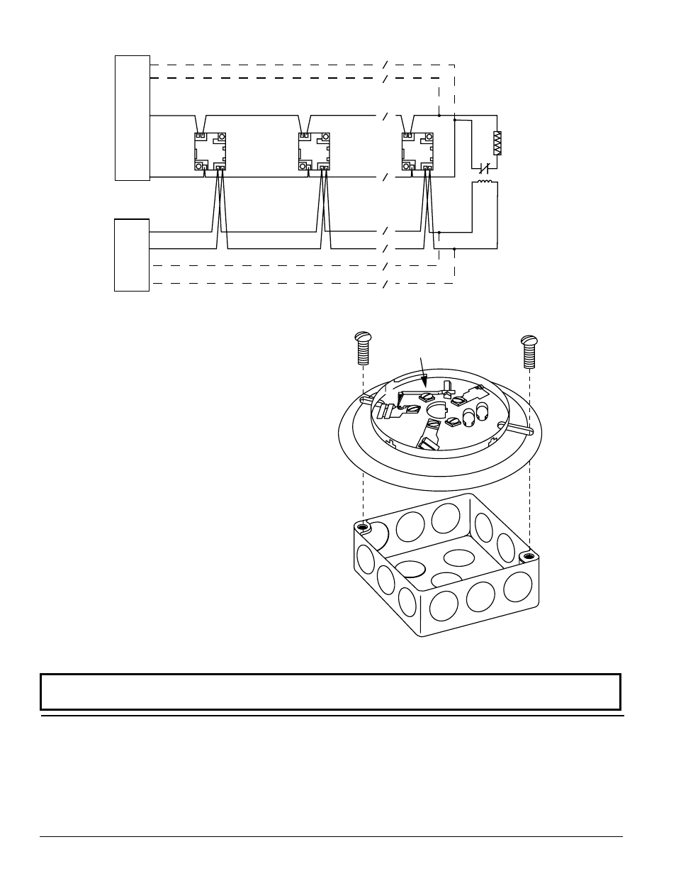
CLASS A OPTIONAL WIRING
UL
LISTED COM
P
A
TIBLE
CONVENTIONAL
CONTROL
P
ANEL
EXTERNA
L
24V
SUPPL
Y
CLASS A OPTIONAL WIRING
UL
LISTED EOL
RESISTOR
UL
LISTED
EOL
RELAY
24V
(+) INIT.
(−) INIT.
(−)POWER
(+)POWER
4 5
2 1
3
4 5
2 1
3
4 5
2 1
3
fIgURE 3. TypICAL WIRINg LAyOUT:
SCREWS
(NOT SUPPLIED)
DETECTOR
BASE
BOX
(NOT SUPPLIED)
SHORTING
SPRING
fIgURE 4. MOUNT BASE TO ELECTRICAL BOx:
C0503-01
WIRINg INSTRUCTIONS
The shorting spring in the base will disengage automatically when the detec-
tor head is removed from the base.
DO NOT remove the shorting spring since it reengages as the detector head is
turned into the base, completing the circuit.
A typical wiring for a two-wire conventional system is shown in Figure 3. Re-
fer to this diagram as needed while wiring the base into the system.
NOTE: Figure 3 shows external 24V supply polarity when the loop system is
in standby (NOT alarming).
MOUNTINg
NOTE: It is recommended that the base be completely wired before mounting.
See Figure 4. Attach the base directly to an electrical box using the screws
supplied with the box. Then, use the plastic screw covers, supplied with the
base, to cover the screws.
The sounder base is 1.1 inches (28 mm) deep. Electrical boxes must be 4
inches (102 mm) square by at least 1-1/2 inches (38 mm) deep; 2-1/8 inches
(54 mm) is recommended.
TESTINg
Before testing, notify the proper authorities that the smoke detector system
is undergoing maintenance and that the system will be temporarily out of
service. Disable the zone or system undergoing maintenance to prevent un-
wanted alarms.
Detectors and bases must be tested after installation and following periodic
maintenance.
Test the B401BH/B401BHA as follows:
1. Test the conventional detector head following the procedure in its manual.
The B401BH/B401BHA should sound approximately 10 seconds after the
detector alarms.
2. Reverse the polarity of the external 24 VDC supply. This should cause every
base in the loop to sound after approximately 10 seconds.
C0956-01
System Sensor warrants its enclosed base to be free from defects in materials and
workmanship under normal use and service for a period of three years from date of
manufacture. System Sensor makes no other express warranty for this base. No agent,
representative, dealer, or employee of the Company has the authority to increase or alter
the obligations or limitations of this Warranty. The Company’s obligation of this Warranty
shall be limited to the repair or replacement of any part of the base which is found to
be defective in materials or workmanship under normal use and service during the three
year period commencing with the date of manufacture. After phoning System Sensor’s
toll free number 800-SENSOR2 (736-7672) for a Return Authorization number, send
defective units postage prepaid to: System Sensor, Repair Department, RA #__________,
Please refer to insert for the Limitations of Fire Alarm Systems
THREE-yEAR LIMITED WARRANTy
3825 Ohio Avenue, St. Charles, IL 60174. Please include a note describing the malfunc-
tion and suspected cause of failure. The Company shall not be obligated to repair or
replace units which are found to be defective because of damage, unreasonable use,
modifications, or alterations occurring after the date of manufacture. In no case shall the
Company be liable for any consequential or incidental damages for breach of this or any
other Warranty, expressed or implied whatsoever, even if the loss or damage is caused by
the Company’s negligence or fault. Some states do not allow the exclusion or limitation of
incidental or consequential damages, so the above limitation or exclusion may not apply
to you. This Warranty gives you specific legal rights, and you may also have other rights
which vary from state to state.
D400-50-00
2
I56-0612-006R
©2010 System Sensor