System Sensor 2312_24TB User Manual
Page 2
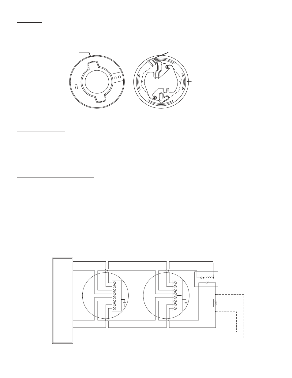
MOUNTING:
Each 2312/24TB detector is supplied with a mounting bracket that permits the detector to be mounted:
1. To a single gang box, or
2. Directly to a 3-1/2 inch or 4 inch octagonal box, or
3. To a 4 inch square electrical box by using a plaster ring.
�����������
������������
���������
���������
��������������������
�������������������������
�����������������������������
���������������������
���
���
�����������������
��������������������
���������������������
S0176-00
Figure 2. 2312/24TB smoke detector mounting bracket
TAMPER RESISTANCE:
This detector includes a tamper-resistant capability that prevents its removal from the bracket without the use of a tool. To make the
detector tamper-resistant, remove the smaller tab by breaking it at the scribed line on the tamper resistant tab before installing the
detector. The tamper resistant tab is on the detector mounting bracket.
To remove a tamper-resistant detector from the bracket, use a pocket screwdriver, or similar tool, to depress the tamper-resistant tab
and turn the detector counterclockwise. The tab is accessible through the slot on the mounting bracket.
WIRING INSTALLATION GUIDELINES:
All wiring must be installed in compliance with the National Electrical Code, applicable local codes, and any special requirements of
the local authority having jurisdiction. Proper wire gauges should be used. The conductors used to connect smoke detectors to control
panels and accessory devices should be color-coded to prevent wiring mistakes. Improper connections can prevent a system from
responding properly in the event of a fire.
The screw terminal block will accept 14 – 22 gauge wire. For best system performance, all wiring should be installed in separate
grounded conduit; do not mix fire system wiring in the same conduit as any other electrical wiring. Twisted pair may be used to provide
additional protection against extraneous electrical interference.
Smoke detectors and alarm system control panels have specifications for allowable loop resistance. Consult the control panel
manufacturer’s specifications for the total loop resistance allowed for the particular model control panel being used before wiring the
detector loops.
Wire connections are made by stripping about 1/4 inch of insulation from the end of the feed wire, inserting the wire into the appropri-
ate terminal, and tightening the screw to secure the wire in place.
S0177-00
Figure 3. Wiring diagram for 2312/24TB detector
�
�
�
�
����
�
�
�
�
�����������������������
������������
������������
�����
������������
���������
�����������
������������
����������
��������������
�����
��
���������
���������
�������
�����
����������
����
�
�
�
�
�
�
�
�
�
�
�
����
�
D300-05-00 2 I56-431-06