Inch or 4-inch octagonal, 1, Inch and 4-inch octagonal box, Make wire connections by stripping about – System Sensor 2400 and 2400TH Direct Wire User Manual
Page 2
D400-05-00 2 I56-285-05R
Mounting
Each 2400 detector is supplied with a mounting bracket kit
that permits the detector to be mounted:
1. Directly to a 3
1
⁄
2
-inch or 4-inch octagonal, 1
1
⁄
2
-inch deep
electrical box, (See Figure 1) or:
2. To a 4-inch square electrical box by using the plaster
ring with the supplied mounting bracket kit.
Installation Wiring Guidelines
All wiring must be installed in compliance with the National
Electrical Code and all applicable local codes, and any spe-
cial requirements of the local authority having jurisdiction.
Proper wire gauges should be used. The conductors used
to connect smoke detectors to control panels and accessory
devices should be color-coded to reduce the likelihood of
wiring errors. Improper connections can prevent a system
from responding properly in the event of a fire.
For signal wiring (wiring between interconnected detec-
tors), wire no smaller than AWG 18 is recommended.
However, the screws and clamping plate in the base can
accommodate wire sizes up to AWG 12. The use of twisted
pair wiring for the power (+ and –) loop is recommended
to minimize the effects of electrical interference.
Smoke detectors and alarm system control panels have
specifications for allowable loop resistance. Consult the
control panel manufacturer’s specifications for the total
loop resistance allowed for the control panel being used
before wiring the detector loops.
S0166-00
TAMPER
RESISTANT
TAB
TO MAKE DETECTOR TAMPER RESISTANT,
BREAK OFF TAB EXTENSION
AT SCRIBED LINE
S0140-00
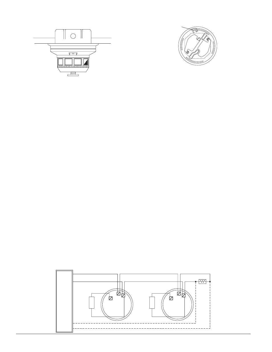
Figure 2. 2400 Smoke detector mounting bracket:
Figure 1. Flush mounting of 2400TH smoke detector
on 3
1
⁄
2
-inch and 4-inch octagonal box:
Figure 3. Wiring diagram for 2400 smoke detector used with two-wire control panel:
+
REMOTE
ANNUNCIATOR
–
+
–
+
REMOTE
ANNUNCIATOR
CLASS A OPTIONAL WIRING
NOTE: IF REMOTE ANNUNCIATOR IS NOT USED, POLARITY TO DETECTOR MAY BE REVERSED.
EOL
RESISTOR
INITIATING
LOOP
UL LISTED
COMPATIBLE
CONTROL
PANEL
+
–
–
–
+
3
2
1
3
2
1
S0141-00
Make wire connections by stripping about
3
⁄
8
inch of insu-
lation from the end of the wire and sliding the bare end
of the wire under the clamping plate, and tightening the
clamping plate screw. A wiring diagram for a typical 2-wire
detector system is shown in Figure 3.
System Sensor’s smoke detectors are marked with a com-
patibility identifier located as the last digit of a five-digit
code stamped on the back of the product. Connect detec-
tors only to compatible control units as indicated in System
Sensor’s compatibility chart which contains a current list of
UL-listed control units and detectors. A copy of this list is
available from System Sensor upon request.
NOTE: For system supervision — do not loop wire under
terminals 1 and 2.
NOTE: If remote annunciator is not used, polarity to
detector may be reversed.
Tamper-resistant Feature
This detector includes a tamper-resistant feature that pre-
vents removal of the detector without the use of a tool. To
make the detector tamper-resistant, break off the smaller
tab at the scribed line on the tamper resistant tab, on the
detector mounting bracket (see Figure 2), then install the
detector. To remove the detector from the bracket once it
has been made tamper resistant, use a small screwdriver to
depress the tamper-resistant tab located in the slot on the
mounting bracket and turn the detector counterclockwise
for removal.