System Sensor 2112_24R and 2112_24TR Photoelectronic User Manual
Page 3
D200-83-00
3
I56-1239-02R
Smoke detectors and alarm system control panels have
specifications for allowable loop resistance. Consult the
control panel specifications for the total loop resistance
allowed for the control panel being used before wiring the
detector loops.
Wire connections are made by stripping about
1
⁄
4
inch of
insulation from the end of the feed wire, inserting the wire
into the appropriate terminal, and tightening the screw to
secure the wire in place.
Installation
Remove power from the control unit or initiating device cir-
cuits before installing detectors.
1. Wire the plug-in screw terminal block per Figure 1 and
plug the terminal block into the detector.
2. Align the arrows on the detector with the arrows on the
mounting bracket.
3. Turn the detector clockwise in the mounting bracket
until it clicks into place.
4. After all detectors have been installed, apply power to
the control unit or initiating device circuits.
5. Test the detector as described in TESTING.
6. Reset the detector at the system control panel.
7. Notify the proper authorities the system is in operation.
Dust covers are an effective way to limit the entry of dust
into smoke detector sensing chambers. However, they may
not completely prevent airborne dust particles from enter-
ing the detector. Therefore, System Sensor recommends the
removal of detectors before beginning construction or other
dust producing activity. Be sure to remove dust covers from
any sensors that were left in place during construction as
part of returning the system to service.
CAUTION
WARNING
IN
T
A
P
T
O
N
O
D
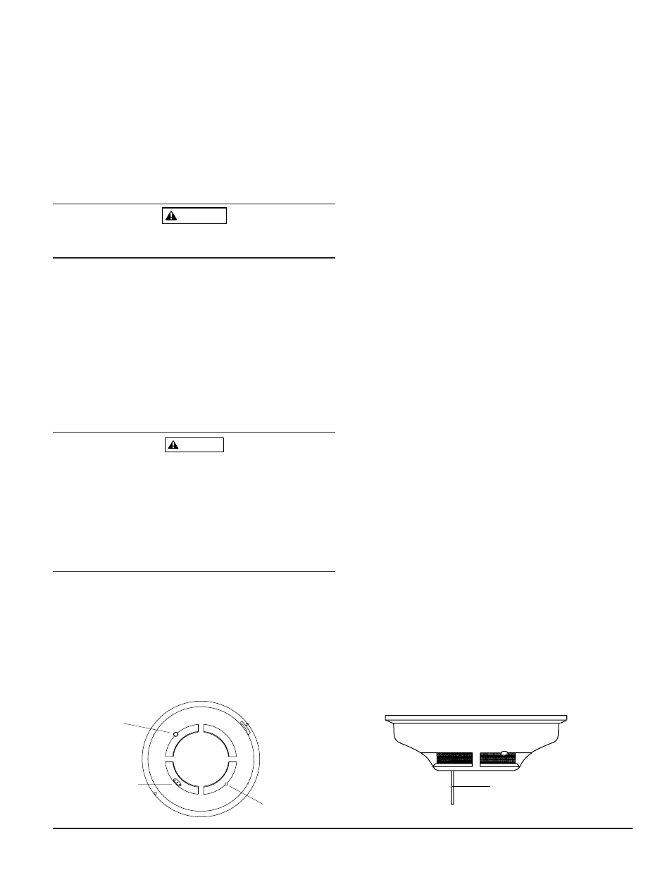
LED
TEST MODULE
SOCKET
RECESSED TEST
SWITCH
PUSH RECESSED
SWITCH WITH A
0.18" MAX. DIAMETER TOOL
Figure 4. Top and side views showing position of test switch:
Testing
NOTE: Before testing, notify the proper authorities that
the smoke detector system is undergoing mainte-
nance and will be temporarily out of service.
Disable the zone or system undergoing mainte-
nance to prevent unwanted alarms.
Detectors must be tested after installation and following
periodic maintenance. Test the 2112/24R and 2112/24TR as
follows:
A. Test Switch
1. A recessed test switch is located on the detector hous-
ing (See Figure 4).
2. Press and hold the recessed test switch with a 0.1 inch
maximum diameter tool such as an allen wrench or
small screwdriver.
3. The detector’s LED should light within 5 seconds.
B. Test Module (System Sensor Model No. MOD400R).
The MOD400R test module can be used with a DMM or
analog voltmeter to check the detector sensitivity as
described in the test module’s manual.
C. Smoke Entry Test
Hold a smoldering punk stick or cotton wick at the side of
the detector and gently blow smoke through the detector
until the unit alarms.
D. Direct Heat Method (Model 2112/24TR only – Hair dryer
of 1000-1500 watts)
Direct the heat toward either of the side thermistors. Hold
the heat source about 12 inches from the detector in order
to avoid damage to the plastic. The detector will reset only
after it has had sufficient time to cool and the power
source has been momentarily interrupted.
Both smoke and heat detection testing are recommended for
verifying system protection capability.
A detector that fails to activate with any of the above tests
should first be cleaned as outlined in MAINTENANCE. If the
detector still fails to activate, return it for repair.
Notify the proper authorities the system is back in operation.
A78-2564-00