System Sensor 2112_24AITR Photoelectronic User Manual
Installation and maintenance instructions
D200-85-00
1
I56-1241-03R
2112/24AITR
Photoelectronic Smoke Detector with
Fixed Heat and Integral Temp-3 Sounder
INSTALLATION AND MAINTENANCE INSTRUCTIONS
3825 Ohio Avenue, St. Charles, Illinois 60174
1-800-SENSOR2, FAX: 630-377-6495
Specifications
Diameter:
5.5 inches (140 mm)
Height (including mounting bracket):
2.05 inches (52 mm)
Weight:
7.5 oz. (210 g)
Operating Temperature Range:
32° to 100°F (0° to 38°C)
Operating Humidity Range:
10% to 93% Relative Humidity, Noncondensing
Latching Alarm:
Reset by momentary power interruption
Audible Signal:
85 dBA minimum when in alarm or with supply polarity reversed
Heat Sensor:
135°F Fixed Temperature Electronic Thermistor
Electrical Ratings
System Voltage (nominal):
12 or 24 VDC
Minimum:
10 VDC
Maximum:
35 VDC
Maximum Ripple Voltage:
30% of nom. Voltage (peak to peak)
Standby Current:
50 µA maximum
Alarm Current:
49 mA typical, 60 mA max. at 12V
57 mA typical, 65 mA max. at 24V
Reset Voltage:
0.8 VDC minimum
Reset Time:
1.0 second maximum
Start-up Time:
30 seconds maximum (after 60 sec. reset)
EOL Relay:
A77-716B, 12/24 VDC
Note: Relay changes only when the thermal alarm state is reached
Alarm Initiation and Auxiliary Relay:
1A @ 30 VAC
Contact Ratings, Resistive Load:
1A @ 30 VDC
Special Considerations:
Due to the built-in temporal pattern, use these detectors only with a non-coded power supply.
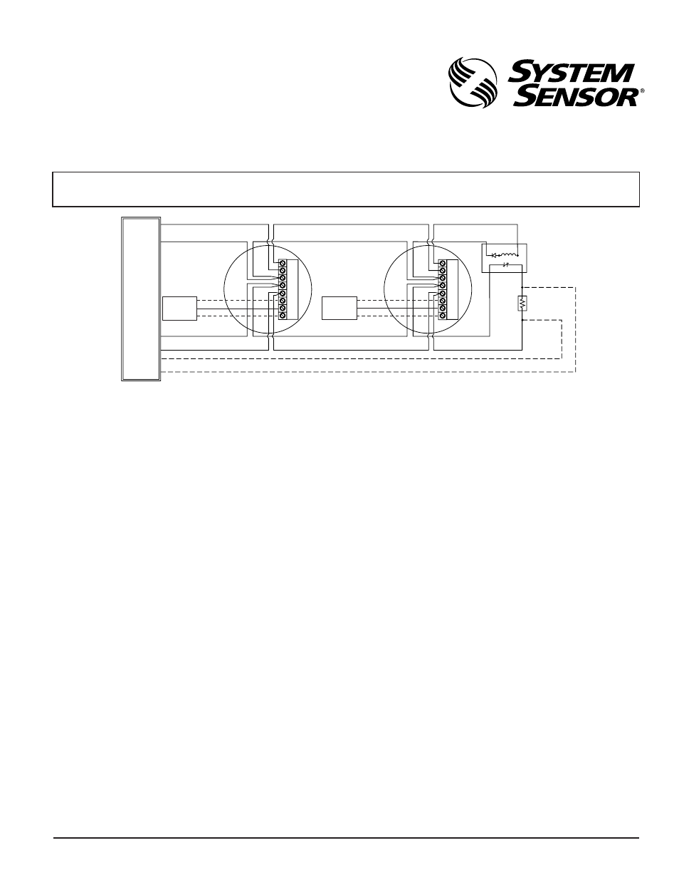
Figure 1. Wiring diagram for the 2112/24AITR detector:
A78-2336-16
Before Installing
Please thoroughly read the System Sensor manual I56-407, Guide for
Proper Use of System Smoke Detectors, which provides detailed informa-
tion on detector spacing, placement, zoning, wiring, and special applica-
tions. Copies of this manual are available at no charge from System
Sensor.
NOTICE: This manual shall be left with the owner/user of this equipment.
IMPORTANT: This detector must be tested and maintained following
NFPA 72 requirements. The detector should be cleaned at least once a
year.
IMPORTANT: OBSERVE POLARITY
As with all sounder models, polarity must be observed on the power connections.
OPTIONAL CLASS A WIRING
EOL RESISTOR
SPECIFIED BY
PANEL
MANUFACTURER
EOL POWER
SUPERVISION
RELAY (SHOWN
ENERGIZED)
A77-716 12/24V
POWER
TO
DETECTORS
UL LISTED
COMPATIBLE
CONTROL
PANEL
INITIATING
LOOP
+
–
P
W
R
A
U
X
P
W
R
A
U
X
+
+
–
A
A
NC
C
NO
+
+
–
A
A
NC
C
NO
ALARM
CONTACT
ALARM
CONTACT
(OPTIONAL)
RELEASING
DEVICE
NC
COMMON
NO
(OPTIONAL)
RELEASING
DEVICE
NC
COMMON
NO