System Sensor 2012H Photoelectronic User Manual
Page 3
D200-75-00
3
I56-1216-02
(If necessary, add an extension ring if the selected box does not have
adequate volume.) The power supply may be mounted remotely from
the detector.
• All wiring must be performed by a licensed electrician and installed in
compliance with the National Electrical Code, applicable local codes,
and any special requirements of the local authority having jurisdic-
tion.
• Use only the specified wire gauge. Maximum interconnect bus length
is 5,000 feet, #14 – 18 AWG cable.
• The detector includes a tamper-resist feature that, when activated,
requires a tool for detector removal. The following detector installa-
tion instructions include how to activate this feature.
Installation Instructions
1. Turn off power at main service panel.
2. Using wire connectors, attach either black wire from power supply to
black ac power wire. Attach other black wire from power supply to
white ac neutral wire.
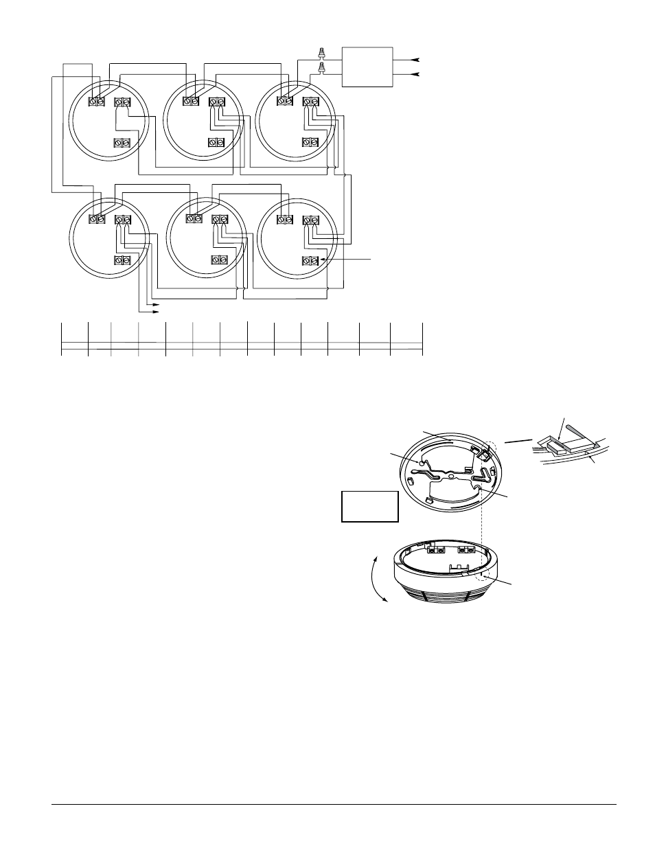
3. Using wire connectors, connect red and gray power supply output
wires to the bus line wires supplying power to the remote detectors.
(See Figure 7.) Use color-coded bus wires.
4. Mount power supply to junction box and cover junction box with a 4″
square box cover, using box mounting screws.
5. Install a junction box where you plan to install the detector. (See type
and size for junction box above.)
6. Install bus line wires from power supply output to junction box. Use
#14-18 AWG wire only. See Figure 7 to determine maximum power bus
length for wire size and number of interconnected detectors.
7. Connect color-coded DC power bus wires to power input screw termi-
nals, located on detector back. If detectors will be interconnected or the
relay used, see following sections for specific installation instructions.
8. Remove detector from mounting bracket by turning the detector coun-
ter-clockwise and pulling the detector away from the bracket.
9. Remove small tab on mounting bracket to activate tamper-resist
feature, if desired. (To release a detector with this feature, push up
on locking tab with screwdriver while turning detector counterclock-
wise.)
10. Install mounting bracket to junction box.
11. Connect power wires to detector(s) as shown in Figure 8. Be sure to
tighten each terminal screw to secure wire in place. Tug wire to be sure
it is connected properly.
12. Attach smoke detector to mounting bracket by aligning arrows on side
of mounting bracket 1-inch to the right of the nib on the detector.
Rotate until the arrow and nib line up. (See Figure 8).
13. After installing all detectors, turn on power at the main service
panel.
14. Check for the green LED to flash about once every 30 to 40 seconds.
This means the detector is receiving power. Check all detectors.
NOTE: If the LED does not flash, power is not getting to the smoke detec-
tor. Check wiring. If LED still does not flash, return the smoke
detector to the manufacturer for repair.
15. Test each detector in the system. (See “Testing” below for more
detailed instructions.)
S0150-00
S0151-00
ALIGNMENT
ARROW
FOR TAMPER RESIST
BREAK OFF TAB HERE
MOUNTING
BRACKET
MOUNTING
SCREW
MOUNTING
SCREW
REMOVE
INSTALL
WHEN INSTALLING:
ALIGN ARROWS ON MOUNTING
BRACKET 1" TO THE RIGHT OF
THE NIB ON THE DETECTOR.
ROTATE UNTIL ARROW AND
NIB LINE UP.
Figure 8:
Dimensions
1-3/4” high
5-1/2” base dia.
Figure 7:
(–)
(+)
INTERCONNECT UP TO
12 DETECTORS
AUXILIARY
ALARM RELAY
12OVAC
A77-727-O1
12VDC POWER
SUPPLY
POWERS UP TO
16 DETECTORS
GRAY
RED
BLACK
BLACK
WIRE
GAUGE
14AWG
16AWG
18AWG
1 UNIT
5000
3735
2349
2 UNITS
2970
1867
1174
3 UNITS
1980
1245
783
4 UNITS
1485
933
587
5 UNITS
1188
747
469
6 UNITS
990
622
391
Maximum power bus length in feet, given number of units (maximum per bus) and wire size.
Maximum interconnect bus length: 5,000 FT., No. 14 – 18 AWG cable.
All wiring must conform to local electrical codes.
Relay contacts rating: 0.5A 30VDC; 0.5A 30VAC
7 UNITS
848
533
335
8 UNITS
742
466
293
9 UNITS
660
415
261
10 UNITS
594
373
234
11 UNITS
540
339
213
12 UNITS
495
311
195
GROUND
SIGNAL
(+) (–)
POWER INPUT
AUXILIARY
GROUND
SIGNAL
(+) (–)
POWER INPUT
AUXILIARY
GROUND
SIGNAL
(+) (–)
POWER INPUT
AUXILIARY
GROUND
SIGNAL
(+) (–)
POWER INPUT
AUXILIARY
GROUND
SIGNAL
(+) (–)
POWER INPUT
AUXILIARY
GROUND
SIGNAL
(+) (–)
POWER INPUT
AUXILIARY