System Sensor 1451 Plug-in Intelligent User Manual
Page 2
D400-01-01
2
I56-0278-008R
1. Install Detectors:
a. Place the detector into the detector base.
b. Turn the detector clockwise until the detector drops
into place.
c. Continue turning detector clockwise to lock it in place.
2. Tamper-proof Feature
The detector bases include a feature that, when acti-
vated, prevents removal of the detector without the use
of a tool. See the installation instruction manual of the
detector base for details in using this feature.
3. After all detectors have been installed, apply power to
the control unit.
4. Test the detector as described under TESTING.
5. Reset the detector at the system control panel.
6. Notify the proper authorities that the system is in operation.
CAUTION
Dust covers can be used to help limit dust entry to the de-
tector, but they are not a substitute for removing the detec-
tor during building construction. Remove any dust covers
before placing system in service.
CAUTION
Smoke detectors are not to be used with detector guards
unless the combination has been evaluated and found
suitable for that purpose.
Testing
Before testing, notify the proper authorities that the smoke
detector system is undergoing maintenance and will tem-
porarily be out of service. Disable the zone or system un-
dergoing maintenance to prevent unwanted alarms.
Detectors must be tested after installation and periodic
maintenance. The 1451 may be tested as follows:
Before testing the detector, look for the presence of the
flashing LEDs. If they do not flash, either power has been
lost to the detector (check the wiring), or it is defective
(return for repair).
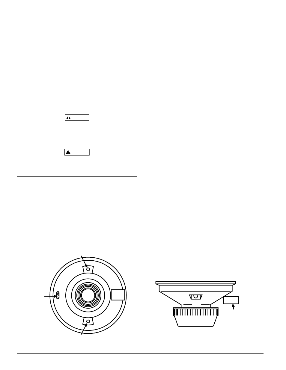
A. Test Magnet (System Sensor Model No. M02-04-00)
1. Place the magnet against the cover opposite the test
module socket. (See Figure 1.)
2. The LEDs on the detector should latch on within
30 seconds.
3. Reset the detector at the system control panel.
B. Test Module (System Sensor Model No. MOD400R)
The MOD400 or MOD400R is used with a digital or an-
alog voltmeter to check the detector sensitivity as de-
scribed in the test module’s manual.
C. Aerosol Generator (Gemini 501)
Set the generator to represent 4%/ft. to 5%/ft. obscura-
tion as described in the Gemini 501 manual. Using the
bowl shaped applicator, apply aerosol until unit alarms.
Notify the proper authorities that the system is back on line.
Detectors that fail these tests should be cleaned as described
under MAINTENANCE and retested. If the detectors still
fail these tests they should be returned for repair.
Figure 1. Bottom and side views showing test magnet position:
PAINTED
SURFACE
TEST
MAGNET
TEST
MAGNET
LED
TEST MODULE
SOCKET
LED
S0137-00