System Sensor DH500 User Manual
Page 3
D500-08-00
3
I56-512-07R
Table 1. Sampling (Inlet) Tubes
Tube
Outside Duct Width
ST-1.5
1 to 2 ft.
(0.3 to 0.6 m)
ST-3
2 to 4 ft.
(0.6 to 1.2 m)
ST-5
4 to 8 ft.
(1.2 to 2.4 m)
ST-10
8 to 12 ft.
(2.4 to 3.7 m)
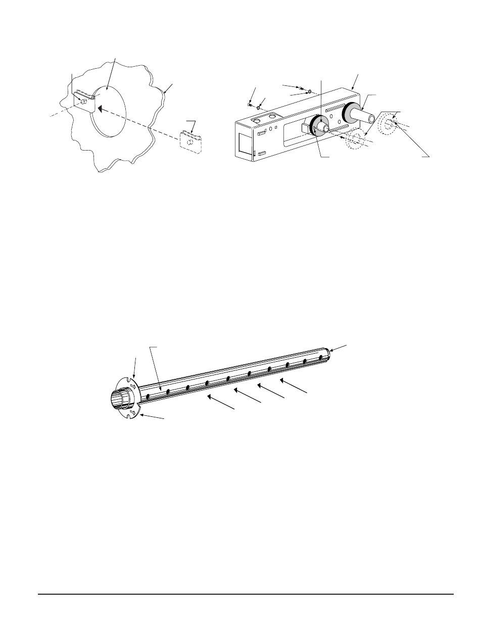
Step 4. Install the Inlet Tube
The inlet tube (shown in Figure 3) is identified by a series
of air inlet holes on the tube. This tube must be purchased
HOLE B
HOLE A
DUCT
WALL
SPEED
NUT
SCREW HOLES FOR ATTACHING
DETECTOR HOUSING TO DUCT
FOAM GASKETS
EXHAUST TUBE
(EXTENSION BUSHING)
DUCT DETECTOR
HOUSING
O-RINGS
MOUNTING
SCREWS
INLET SAMPLING
TUBE BUSHING
Figure 2A. Speed nut mounting location:
H0116-00
A78-2045-00
Figure 2B. Installation of foam gaskets over sam-
pling tube bushings:
separately. Order the correct length, as specified in Table 1,
for the width of the duct where it will be installed. The
exhaust tube is molded into the base of the duct housing.
The inlet tube is always installed in the right house bush-
ing, with the air inlet holes facing into the air flow. To
assure proper installation, the tube mounting flange is
marked with arrows. Mount the inlet tube so that the
arrows point into the air flow. Figure 4 shows the various
combinations of tube mounting configurations with respect
to air flow.
A. Installation for Ducts Less Than 8 Feet Wide
1. If the inlet tube is longer than the width of the air duct,
drill a 3/4-inch hole in the duct directly opposite the
hole already cut for the inlet tube.
If the inlet tube is shorter than the width of the air duct,
install the end cap into the inlet tube (see Figure 3).
2. Slide the inlet tube into the right housing bushing.
Position the tube so that the arrows point into the air
flow.
3. Secure the tube flange to the housing bushing with the
two #6 self-tapping screws.
4. For tubes longer than the width of the air duct, the tube
should extend out of the opposite side of the duct. If
INLET
TUBE
END
PLUG
AIR HOLES
ARROWS
MUST FACE
INTO AIR FLOW
AIR FLOW DIRECTION
FLANGE
A78-2047-01
Figure 3. Air duct detector inlet sampling tube:
there are more than 2 holes in the section of the tube
extending out of the duct, select a different tube length
using Table 1. Otherwise, trim the end of the tube pro-
truding through the duct so that 1 to 2 inches of the tube
extends outside the duct. Plug this end with the tube
end plug and tape closed any holes in the protruding
section of the tube. Be sure to seal the duct when the
tube protrudes.
5. Any inlet tube over 3 feet long must be supported on the
opposite side of the duct detector housing.