System Sensor DH400ACDCIHT User Manual
Page 4
Install the inlet tube as follows:
1. Drill a 3/4-inch hole in the duct directly opposite the
hole already drilled for the inlet tube.
2. Slide the inlet tube with the flange into the centermost
housing bushing. Position the tube so that the arrows
point into the air flow. Secure the tube flange to the
housing bushing with two #6 self-tapping screws.
3. From inside the duct, couple the other section of the
inlet tube to the section already installed using the 1/2-
inch conduit fitting supplied. Make sure that the holes
on both of the air inlet tubes are lined up and facing into
the air flow.
4. Trim the end of the tube protruding through the duct so
that 1 to 2 inches of the tube extend outside the duct.
Plug this end with the end plug and tape closed any
holes in the protruding section of the tube. Be sure to
seal the duct when the tube protrudes.
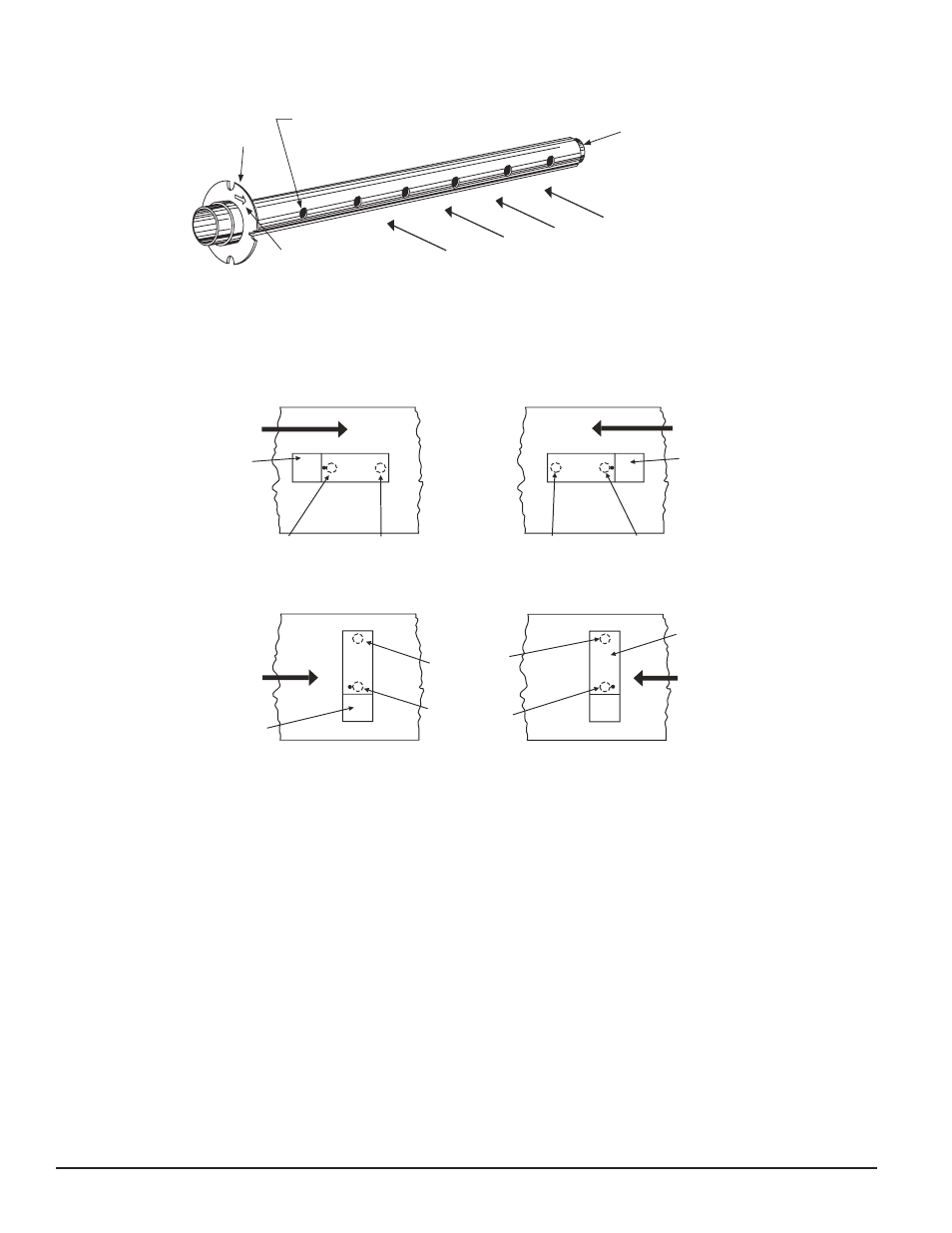
Figure 4. Air duct detector inlet sampling tube:
SAMPLING
TUBE
END CAP
AIR HOLES
ARROW
MUST FACE
INTO AIR FLOW
AIR FLOW DIRECTION
FLANGE
H0108-02
AIR FLOW
DIRECTION
DETECTOR
HOUSING
DOTS INDICATE POSITION OF
SAMPLING TUBE HOLES
AIR FLOW
DIRECTION
DETECTOR
HOUSING
SAMPLING
TUBE
EXHAUST
TUBE
AIR FLOW
DIRECTION
EXHAUST
TUBE
SAMPLING
TUBE
SAMPLING
TUBE
EXHAUST
TUBE
DETECTOR
HOUSING
AIR FLOW
DIRECTION
DETECTOR
HOUSING
A.
B.
C.
D.
HORIZONTAL MOUNTING OF HOUSING
VERTICAL MOUNTING OF HOUSING
Figure 5. Tube mounting configurations with varying air flow direction:
H0109-01
NOTE: An alternate method to using the ST-10 is to use
two ST-5 inlet tubes. Remove the flange from
one of the tubes and install as described above.
After the installation, use electrical tape to close
off some of the sampling holes so that there is a
total of 10 to 12 holes spaced as evenly as possible
across the width of the duct.
Air currents inside the duct may cause excessive vibration,
especially when the longer sampling tubes are used. In
these cases a 3 inch floor flange (available at most plumb-
ing supply stores) may be used to fasten the sampling tube
to the other side of the duct. When using the flange/con-
nector mounting technique, drill a 1 inch to 1-1/4-inch hole
where the flange will be used.
D400-64-00 4 I56-991-08R