System Sensor DH100 User Manual
Page 3
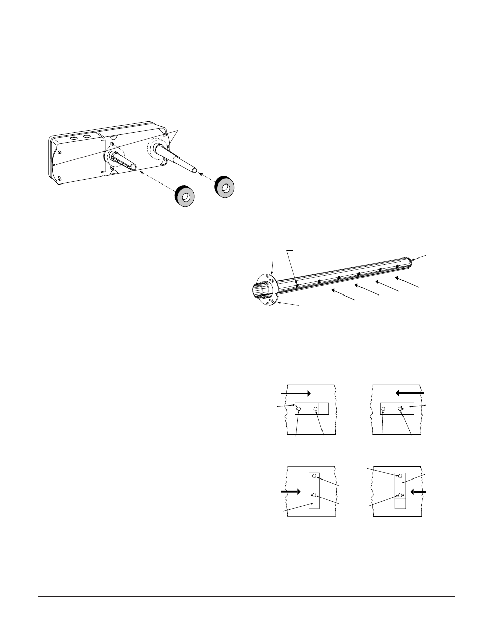
[5.3] Secure The Detector Housing To The Duct
Slide the foam gaskets over the tube bushings as shown in
Figure 3. Use the two 11/4" long sheet metal screws to
screw the detector housing to the duct.
CAUTION: Do not overtighten the screws.
Figure 3. Installation of foam gaskets over sampling
tube bushings:
A78-2045-00
[5.4] Sampling Tube Installation of Ducts Greater
Than 1
1
⁄
2
Feet Wide
The sampling tube is identified by a series of air inlet holes
on the tube. One plastic tube is included for ducts up to 18
″
in width. All other lengths must be purchased separately.
Order the correct length, as specified in Table 1, for width
of the duct where it will be installed. The exhaust tube is
molded onto the base of the duct housing, and the
A2440-00 Exhaust Tube Extension is available as an acces-
sory in those cases where the molded exhaust port does not
extend at least 2 inches into the duct.
The inlet tube is always installed with the air inlet holes
facing into the air flow. To assist proper installation, the
tube’s mounting flange is marked with arrows. Make sure
the inlet tube is mounted so that the arrows point into the
air flow (see Figure 4). Figure 5 shows the various combi-
nations of tube mounting configurations with respect to air
flow. Mounting the detector housing in a vertical orienta-
tion is acceptable, provided that the air flows directly into
the sampling tube holes as indicated in Figure 4.
Table 1. Inlet tubes required for different duct
widths:
Outside Duct Width
Inlet Tube Required
1 to 2 ft.
ST-1.5
2 to 4 ft.
ST-3
4 to 8 ft.
ST-5
8 to 12 ft.
ST-10
[5.4.1] Installation For Ducts Greater Than 1
1
⁄
2
Feet
But Less Than 8 Feet Wide
1. If the tube is longer than the width of the air duct, drill a
3
⁄
4
-inch hole in the duct opposite the hole already cut for
the inlet tube. Make sure the hole is 1
″ to 2″ below the
SCREW HOLES FOR
ATTACHING HOUSING
TO DUCT WORK.
inlet hole on the opposite side of the duct to allow for
moisture drainage. If the tube is shorter than the width of
the air duct, install the end plug into the inlet tube as
shown in Figure 4. Sampling tubes over 3 ft. long must be
supported at the end opposite the duct detector.
2. Slide the tube into the housing bushing that meets the
air flow first. Position the tube so that the arrows point
into the air flow.
3. Secure the tube flange to the housing bushing with two
#6 self-tapping screws.
4. For tubes longer than the width of the air duct, the tube
should extend out of the opposite side of the duct. If
there are more than 2 holes in the section of the tube
extending out of the duct, select a different length using
Table 1. Otherwise, trim the end of the tube protruding
through the duct so that 1
″ to 2″ of the tube extend out-
side the duct. Plug this end with the end plug and tape
closed any holes in the protruding section of the tube. Be
sure to seal the duct when the tube protrudes.
Figure 4. Air duct detector inlet sampling
A78-2047-00
Figure 5. Tube mounting configurations with varying
air flow direction:
AIR FLOW
DIRECTION
DETECTOR
HOUSING
DOTS INDICATE POSITION OF
SAMPLING TUBE HOLES
AIR FLOW
DIRECTION
DETECTOR
HOUSING
INLET
TUBE
EXHAUST
TUBE
AIR FLOW
DIRECTION
EXHAUST
TUBE
INLET
TUBE
INLET
TUBE
EXHAUST
TUBE
DETECTOR
HOUSING
AIR FLOW
DIRECTION
EXHAUST
TUBE
INLET
TUBE
DETECTOR
HOUSING
A.
B.
C.
D.
HORIZONTAL MOUNTING OF HOUSING
VERTICAL MOUNTING OF HOUSING
INLET
TUBE
END
PLUG
AIR HOLES
ARROWS
MUST FACE
INTO AIR FLOW
AIR FLOW DIRECTION
FLANGE
D100-67-00
3
I56-1148-08R
A78-1812-08
NOTE: Only metal sampling tubes may be used on ori-
entations C and D.