Figure 2. application examples, Step 3. drill the mounting holes, Step 4. mount duct housing – System Sensor 7251DH User Manual
Page 2: Table 1. sampling (inlet) tubes
SS-400-000
2
I56-3065-000R
Each 7251DH duct smoke detector should be mounted as follows:
1. Location: Mount detector on the room side (up stream) of any
air filter. NOTICE: Mounting detector after filter may filter out
smoke particles and is not recommended.
2. Coverage: Each detector pipe length should be mounted
along the longer direction of the return air opening (length
direction). One detector and one standard, pre-drilled pipe
length should be installed for every 2ft of return air open-
ing width. When more than one detector is required (widths
greater than 2ft.), detector housings should be staggered on
opposite ends of the opening length. (refer to illustration).
3. Hole Direction: holes facing directly into flow for positive
pressure effect
4. Insure adequate pressure differential across the detector hous-
ing according to step 8.1 of this document.
Figure 2. APPLICATION EXAMPLES:
3ft
1
2ft
CENTER
7ft
2ft
2
1
2
3
“LENGTH”
TYPIC
C0931-00
H0545-00
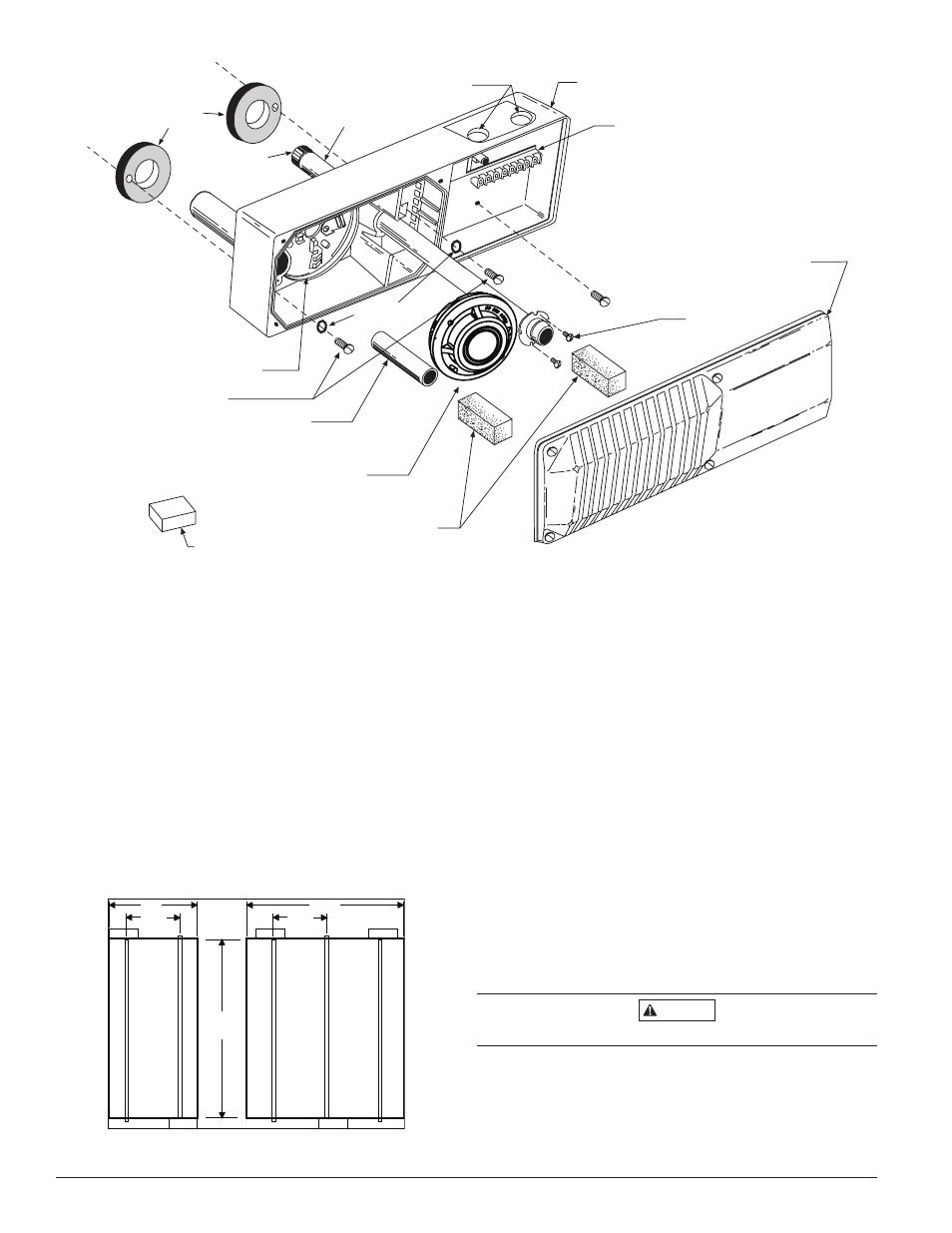
SAMPLING TUBE
FILTERS
CONDUIT HOLES
DUCT DETECTOR
HOUSING
TERMINAL STRIP
DUCT DETECTOR
COVER
SAMPLING TUBE
MOUNTING
SCREWS
DETECTOR HEAD
(SUPPLIED SEPARATELY)
EXHAUST
FILTER ADAPTER
DETECTOR BASE
INLET SAMPLING TUBE
(SUPPLIED SEPARATELY)
O-RINGS
FOAM
GASKETS
HOUSING
MOUNTING SCREWS
TEST MAGNET
TUBE
END
PLUG
Figure 1:
Step 2. Verify Duct Air Flow Direction and Velocity
The 7251DH is designed to be used in air handling systems having
air velocities of 300 to 4000 feet per minute. Be sure to check en-
gineering specifications to ensure that the air velocity in the duct
falls within these parameters. If necessary, an Alnor Model 6000-
P velocity meter, Dwyer 460 differential pressure gauge, or their
equivalent, may be used to check the air velocity in the duct.
Step 3. Drill the Mounting Holes
Remove the paper backing from the top and bottom of the tem-
plate. Affix the template to the air duct at the desired mounting
location. Make sure the template lies flat and smooth on the air
duct. Center punch hole targets and remove the template. Drill the
holes as indicated on the template. Slide the two speed nuts over
the two small holes (Hole A) next to the sampling tube bushing
holes (Hole B) previously drilled in the duct (See Figure 3A).
Step 4. Mount Duct Housing
Remove the duct housing cover. Slide the foam gaskets over the
tube bushings as shown in Figure 3B. Make sure the two small
holes in the gaskets line up with the two base mounting holes. Put
one
5
/
16
˝ O-ring over each of the two #10 sheet metal screws. Use
the two sheet metal screws to secure the duct housing to the duct.
CAUTION
Do not overtighten the screws.
Table 1. Sampling (Inlet) Tubes
Tube
Outside Duct Width
ST-1.5 1 to 2 ft. (0.3 to 0.6 m)
ST-3
2 to 4 ft. (0.6 to 1.2 m)
ST-5
4 to 8 ft. (1.2 to 2.4 m)
ST-10
8 to 12 ft. (2.4 to 3.7 m)