Correct – System Sensor SP3R1224MC and SP3W1224MC User Manual
Page 2
Example: Assume you have 10 devices on a zone and each
requires 50 mA average and 2000 Ft. of 14 AWG wiring (to-
tal length=outgoing+return). The voltage at the end of the
loop is 0.050 amps per device × 10 devices × 3 ohms/1,000
ft. × 2000 ft =3 volts drop.
The same number of devices using 12 AWG wire will pro-
duce only 2 volts drop. The same devices using 18 AWG
wire will produce 8 volts drop. Consult your panel manu-
facturer’s specifications, as well as SpectrAlert’s operating
voltage range to determine acceptable voltage drop.
Note: If class “A” wiring is installed, the wire length may be
up to 4 times the single wire length in this calculation.
Installation
All wiring must be installed in compliance with the Na-
tional Electrical Code (NEC) and applicable local codes as
well as special requirements of the authority having juris-
diction, using the proper wire size. This also includes all
applicable NFPA Standards, ANSI/UL 1480, UL 1971 and
NEC 760.
Electrical
1. Connect the speaker/strobe as shown in Figure 1. Keep
in mind that even though the speaker and strobe are
a single mechanical unit, they are electrically indepen-
dent and require separate power sources.
NOTE: Do NOT loop electrical wiring under terminal
screws. Wires connecting the device to the control panel
must be broken at the device terminal connection in order
to maintain electrical supervision.
Figure 1. Electrical connections:
TO NEXT
STROBE OR EOL
INPUT FROM
POWER SUPPLY
INPUT FROM
AMPLIFIER
TO NEXT
SPEAKER OR EOL
STROBE
SPEAKER
NOTE: Supply power for strobe must be continuous for
proper operation.
A0101-00
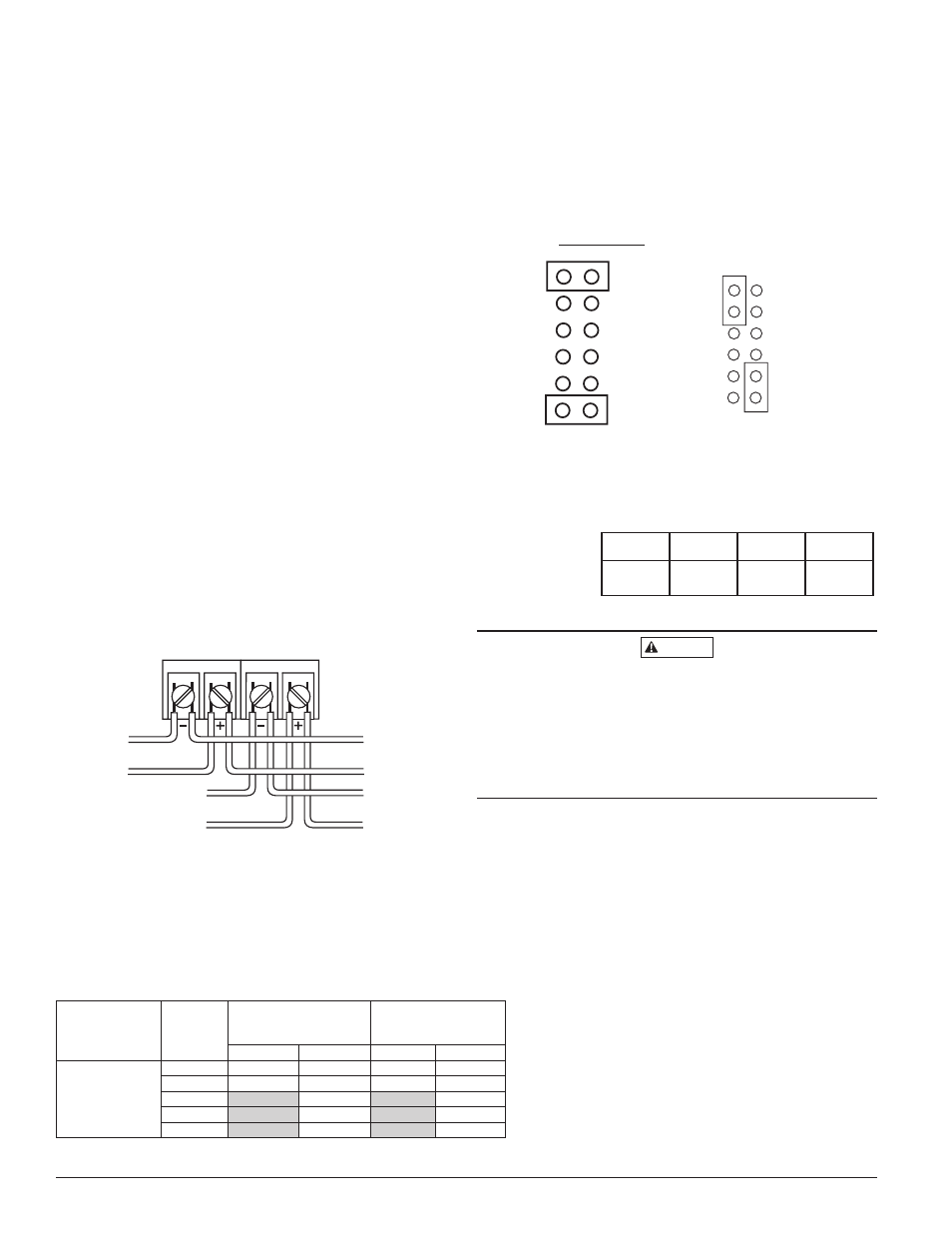
2. See Figure 2 as an example of how to select a 1⁄4 Watt
input when a 25 volt amplifier is being used. Notice that
the header, SW1, has two shunts. One shunt is used to se-
lect either 25 or 70.7 volts input. The other shunt is used
to select input power of 1⁄4, 1⁄2, 1 or 2 Watts. Table 1
lists the UL reverberant and anechoic output sound levels
for each power tap on the SP3 series speaker/strobes.
Figure 2. Speaker Voltage and Power Selection:
25.0V
70.7V
2W
1W
1/2W
1/4W
25.0V
70.7V
2W
1W
1/2W
1/4W
CORRECT
SW1
SW
1
INCORRECT
Table 1. Sound levels for each transformer power tap:
2W
1W
1/2W
1/4W
89
87
84
81
UL
Reverberent
(dBS @10 ft.)
CAUTION
Signal levels exceeding 130% rated signal voltage can dam-
age the speaker. Consequently, an incorrect tap connection
may cause speaker damage. This means that if a 25V tap
is selected when a 70.7V amplifier is being used, speaker
damage may result. Therefore, be sure to select the proper
taps for the amplifier voltage/input power level combina-
tion being used.
D900-42-00
2
I56-2811-000R
A0102-00
Table 2. Strobe current draw measurements – 12/24 Volt applications:
NOTE: All models were only tested at the 8-17.5 and 16-33 Volt-FWR/DC limits. This does not include the 80% low-end
or 110% high-end voltage limits.
Model No.
Candela
Setting
FWR Operating
Current–Strobe
(mA RMS)
DC Operatng
Current–Strobe
(mA RMS)
12V
24V
12V
24V
Speaker/Strobe
SP3R1224MC
SP3W1224MC
15
112
64
127
59
15/75
135
74
127
69
30
93
90
75
158
160
110
208
209