System Sensor SP2R1224MCK User Manual
Page 3
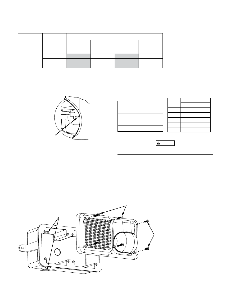
Viewing Window
D900-40-00
3
I56-2609-002R
A0133-00
Candela Selections:
Figure 3. For strobe candela selections, adjust slide
switch located on the rear of the product while
watching the viewing window on the side of the
reflector.
NOTE: SpectrAlert Selectable Output strobes, set at 15 and
15/75cd, automatically work on both 12V and 24V
power supplies.
NOTE: The strobe is not listed for 12V operating voltages
when set to 30, 75 or 110 candela. Use only those
settings marked as OK in this chart:
WARNING
When using a 12V panel, this device will yield required
light output only in the 15 or 15/75 candela setting.
Table 2. Strobe current draw measurements – 12/24 Volt applications:
NOTE: All models were only tested at the 8-17.5 and 16-33 Volt-FWR/DC limits. This does not include the 80% low-end
or 110% high-end voltage limits.
Model No.
Candela
Setting
FWR Operating Current–Strobe
(mA RMS)
DC Operating Current–Strobe
(mA RMS)
12V
24V
12V
24V
SP2R1224MCK
Speaker/Strobe
15
112
64
127
59
15/75
135
74
127
69
30
93
90
75
158
160
110
208
209
Figure 4.
Mounting
1. Mount outdoor back box (supplied with product) in
desired location (see Figure 4).
2. Install
3
/
4
˝ NPT plug into unused conduit opening.
3. Complete field wiring.
4. Mount speaker to back box using 4 #8-32 × 1
3
/
8
˝ and 2
#8-32 ×
3
/
4
˝ screws supplied with product.
NOTE: The outdoor notification appliance must be used
with the outdoor back box when installed in appli-
cations requiring the appliance to be outdoor-listed.
In such applications, using a back box other than
the outdoor back box supplied with the product will
void the UL designation.
3
/
4
˝ NPT
Conduit
Entrance
1
3
/
8
˝ screws (4)
3
/
4
ʺ
screws
A0347-00
Candela equivalent at –40°C
and below:
15cd
3cd
15/75cd
20cd
30cd
9cd
75cd
27cd
110cd
46cd
Permissible Candela Settings:
Candela
Setting
Operating Voltage
12V
24V
15
OK
OK
15/75
OK
OK
30
OK
75
OK
110
OK