System Sensor SP2C Series Ceiling Mount Speaker_Strobes User Manual
Page 3
Signal levels exceeding 130% rated signal voltage can dam-
age the speaker. Consequently, an incorrect tap connection
may cause speaker damage. This means that if a 25V tap is
selected when a 70.7V amplifier is being used, speaker damage
may result. Therefore, be sure to select the proper taps for the
amplifier voltage/input power level combination being used.
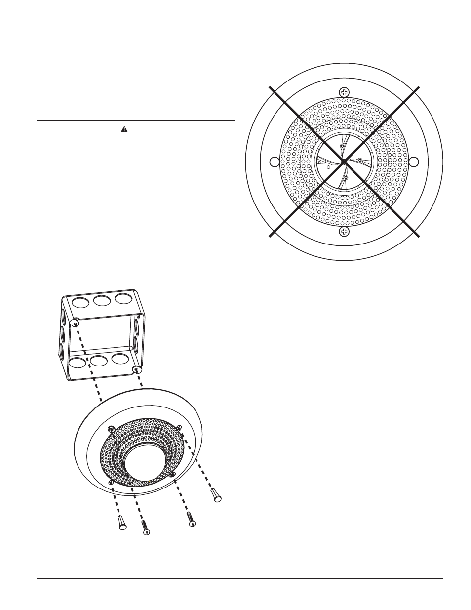
Mounting
The SP2C series ceiling mount speaker/strobe can be flush
mounted on a 4
˝
Ч 4
˝
Ч 2
1
/
8
˝
back box. Use two 8-32 × 1
3
/
4
˝
pan
head screws to attach the speaker to the back box (See Fig. 3).
CAUTION
D690-02-00
3
I56-1455-009R
Figure 3: Flush mount back box
Figure 4: Positioning for maximum brightness
NOTE: For maximum brightness, unit must be mounted with
flash angles as shown.
2. See Figure 2 as an example of how to select a
1
/
4
Watt
input when a 25 volt amplifier is being used. Notice that
the header, SW1, has two shunts. One shunt is used to
select either 25 or 70.7 volts input. The other shunt is
used to select input power of
1
/
4
,
1
/
2
, 1 or 2 Watts. Table 1
lists the UL reverberant and anechoic output sound lev-
els for each power tap on the SP2C series ceiling mount
speaker/strobes.
Note: Any combination of 4˝×4˝
back box and extension ring may
not exceed a depth of 3
5
/
8
˝.
A0161-01
A0160-00
FILL
PLUGS