System Sensor SP100 Series Dual Transformer Speakers and Speaker_Strobes User Manual
Page 3
D400-40-00
3
I56-609-03
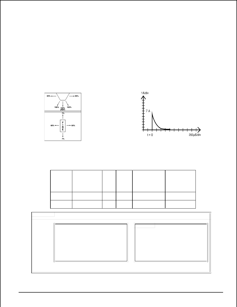
Figure 3:
Table 2. Strobe characteristics:
Figure 4. 24 V Strobe in-rush current:
Notes:
1. Legend:
SP100 = Round grille speaker
Example:
SP101 = Square grille speaker
SP101R24M
W = white
| | | |
R = red
| | | |_ M = 15 candela strobe
24 = 24 Volt Strobe
| | |___ 24 = 24 volt strobe
LO = 1.5 candela strobe
| |____ R = Red
M = 15 candela strobe
|______ SP101 = Square grille speaker
2. SP100*24LOC or SP100*24MC ships with ceiling mount strobe.
3. SP101*24LO or SP101*24M ships with wall mount strobe.
Model
Number
Description
Supply
Voltage
(VDC)
Max.
Current
@ Listed
Voltage
Operating Current
@ Rectified
Unfiltered
Voltage
Min. Light
Output @ 100%
Veiwing Angle
(See Fig. 3)
SP10**24LO
SP10**24M
speaker w/ strobe
speaker w/ strobe
24
24
25 mA
25 mA
45 mA rms
125 mA rms
1.5 cd
15 cd
Strobe Light Ratings
The signaling strobe is rated for 0
°
to 49
°
C and is not suit-
able for outdoor use.
See Figure 3. The light output of the SP10**24LO is 1.5 cd
minimum when it is viewed from the front. The light out-
put of the SP10**24M is 15 cd minimum when it is viewed
from the front.
Under no circumstances can the strobe input voltage ex-
ceed 33 VDC or be less than 18 VDC.
To calculate battery requirements, use the current values
shown in Table 2. However, note that there is an in-rush
current associated with strobe power-up. This information
may be used in consideration of fuse selection.
For the 24V strobe, as shown in Figure 4, the in-rush cur-
rent typically peaks at 7.0A, then drops to nominal in
800
µ
S.