Figure 5: horns and strobes powered in tandem, Figure 3: horn factory default setting, Tandem operation – System Sensor S1224MCK, P1224MCK and H12_24K User Manual
Page 3: Independent operation, Permissible candela settings
System Operation – Non-Synchronized Devices:
Figure 4a. Any combination of models powered by a
2-wire circuit:
HORN
(+)
(–)
(+)
(–)
E
O
L
(+)
(–)
(+)
(–)
HORN/STROBE
STROBE ONLY
TWO WIRE SYSTEM
ANY MIX OF MODELS
WIRED FOR TANDEM
OPERATION
HORN
SYNCHRONIZATION MODULE
MDL
(+)
(–)
(+)
(–)
E
O
L
(+)
(–)
(+)
(–)
HORN/STROBE
STROBE ONLY
TWO WIRE SYSTEM
ANY MIX OF MODELS
WIRED FOR TANDEM
OPERATION
System Operation – Synchronized Devices:
Figure 4b. Any combination of models powered by a
2-wire circuit:
HORN
(+)
(–)
(+)
(–)
E
O
L
(+)
(–)
(+)
(–)
HORN/STROBE
STROBE ONLY
TWO WIRE SYSTEM
ANY MIX OF MODELS
WIRED FOR TANDEM
OPERATION
HORN
SYNCHRONIZATION MODULE
MDL
(+)
(–)
(+)
(–)
E
O
L
(+)
(–)
(+)
(–)
HORN/STROBE
STROBE ONLY
TWO WIRE SYSTEM
ANY MIX OF MODELS
WIRED FOR TANDEM
OPERATION
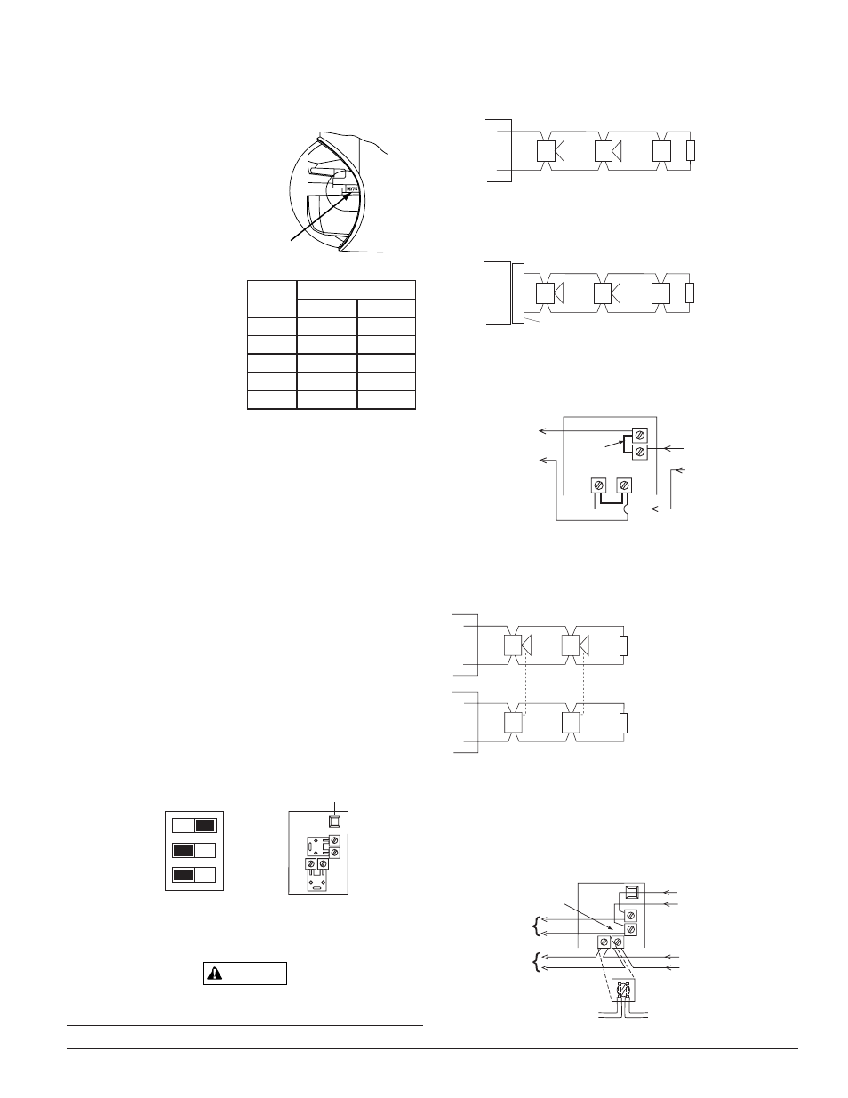
Figure 5: Horns and strobes powered in tandem:
NOTE: Supply power must be continuous for proper operation.
FROM:
FACP, MODULE
OR PREVIOUS
DEVICE
TO NEXT
DEVICE OR
EOL
+
–
Strobe +
Strobe – Horn –
Horn +
TANDEM OPERATION
HORN/STROBE COMBO
FACTORY
INSTALLED
JUMPERS
Figure 6: Any combination of models powered by a 4-
wire circuit to provide independent horn and strobe op-
eration (remove factory installed jumpers, see Figure 8):
(+)
(–)
(+)
(–)
(+)
(–)
FOUR WIRE SYSTEM
COMBO MODELS
WIRED FOR INDEPENDENT
OPERATION
(HORN CAN BE TURNED OFF
AT THE PANEL WHILE STROBES
CONTINUE TO OPERATE)
E
O
L
(+)
(–)
(+)
(–)
(+)
(–)
E
O
L
S
T
R
O
B
E
C
O
M
B
O
H
O
R
N
H
O
R
N
S
T
R
O
B
E
Figure 7: Horns and strobes powered indepen-
dently (horn operated on coded power supply):
NOTE: Strobes must be powered continuously for horn operation.
FROM:
FACP, MODULE (MDL)
OR PREVIOUS
DEVICE
Break wire as shown for
supervision of connection.
DO NOT allow stripped wire
leads to extend beyond switch
housing. DO NOT loop wires.
TO NEXT
DEVICE OR
EOL
INDEPENDENT OPERATION
HORN AND STROBE
TO NEXT
DEVICE OR
EOL
STROBE +
HORN +
STROBE +
STROBE –
STROBE –
HORN –
HORN –
HORN +
FACTORY INSTALLED
JUMPER WIRES REMOVED
NOTE: STROBES MUST
BE POWERED CONTINUOUSLY
FOR HORN OPERATION.
Candela Selections:
Figure 2: For strobe candela selection, adjust slide
switch located on the rear of the product while watch-
ing the viewing window on the side of the reflector.
NOTE: SpectrAlert selectable out-
put strobes, set at 15 and 15/75cd,
automatically work on both 12V
and 24V power supplies.
NOTE: The strobe is not listed
for 12V operating voltages when
set to 30, 75 or 110 candelas.
Use only those settings marked
as OK in this chart:
Horn selections using 3-position DIP switch on horn/
strobe (refer to Figure 3):
NOTE: When powered from a FWR supply, the horn will be mod-
ulated (turned on and off) by 120Hz causing it to sound different
than if powered by a DC supply.
High/Low Volume
ON=High Volume, OFF=Low Volume
NOTE: The low volume setting of some tones must NOT be used
for public mode applications when the device is powered from a 12-
volt panel. Refer to the Sound Output Guide on the previous page.
Temp/Non-Temp
ON=NON-Temporal, OFF=Temporal
3KHz/Electromechanical
ON=3KHz, OFF=Electromechanical
Figure 3: Horn Factory Default Setting:
The factory default setting is High, Temporal 3, and Electrome-
chanical tone.
Low
OFF
ON
Temporal
Electromech.
DIP Switch
Factory
Default
High
Non-Temporal
3000Hz
Base (rear)
WARNING
Check terminal polarity before wiring. For proper operation, make
sure the correct wire polarity is applied to the unit.
D900-37-00
3
I56-2257-005R
A0110-00
A0111-00
A0112-00
Viewing Window
A0133-00
Permissible Candela Settings:
Candela
Setting
Operating Voltage
12V
24V
15
OK
OK
15/75
OK
OK
30
OK
75
OK
110
OK
A0111-00
NOTE: Strobes must be
powered continuously
for horn operation.
A0113-00
A0114-00