Screw types used for mounting, Independent operation – System Sensor P1224 and S1224 User Manual
Page 4
PLASTIC SNAP LEVER
TAB SLOT
TAB
INSERT REMOVAL TOOL
D900-28-00
4
I56-1796-011R
© 2005 System Sensor
4-INCH BACK BOX
WALL OPENING MUST
EQUAL PLATE OPENING
LOCKING RIB SLOT
LOCKING RIB
D-MP, D-MPW, D-MP-FC, D-MPW-FC
A
A
Strobe or Horn/Strobe with universal mounting plate:
Strobe or Horn/Strobe surface mount:
Mounting Diagrams:
Strobe or Horn/Strobe with small footprint
mounting plate:
4-INCH BACK BOX
BBS, BBSW
LOCKING RIB SLOT
A
A
LOCKING RIB
Screw types used for mounting:
A = 8-32 x
3
⁄
4
flat head
B = 6-32 x 1
5
⁄
16
pan head
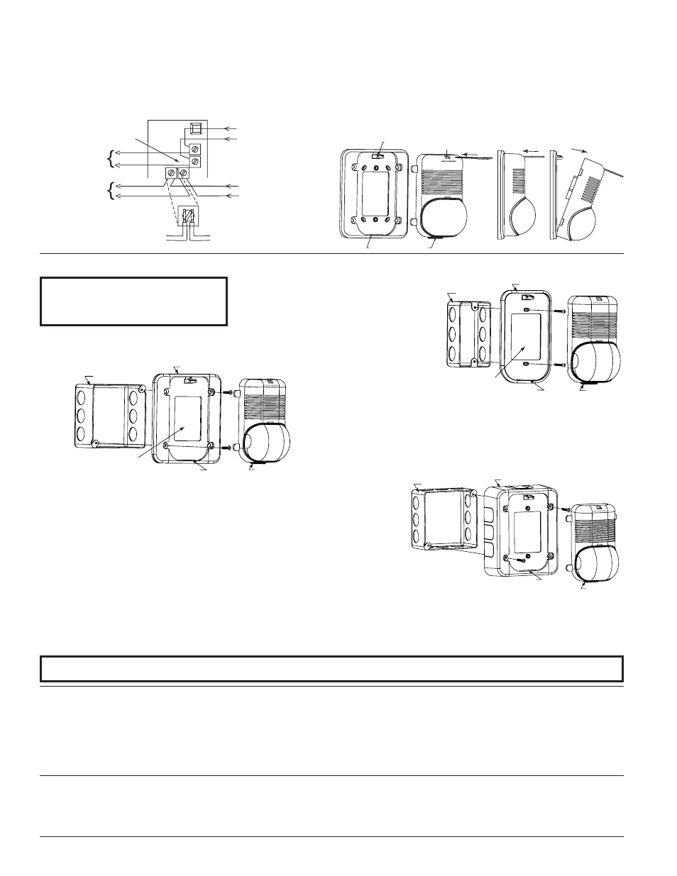
1. Mount plate to back box using screws B.
2. Break off four tabs from unit.
3. Complete field wiring, making sure wall opening is large enough for
terminals to fit through.
4. Insert locking rib into slot on plate.
5. Press into plate; unit will make a “click” when it has locked into place.
1. Mount plate to back box using screws A, making sure wall
opening is equal to the plate opening.
2. Complete field wiring.
3. Insert locking rib into slot on plate.
4. Press into plate, unit will make a “click” when it has locked
into place.
1. Mount skirt to back box with screws A.
2. Complete field wiring.
3. Insert locking rib on unit into slot on skirt.
4. Press into skirt; unit will make a “click” when it has locked into place.
(NOTE: Strobe and skirt may also be mounted to a 2-inch box using
screws B instead of screws A.)
A0116-00
A0117-00
A0115-00
A0118-00
Three-Year Limited Warranty
System Sensor warrants its enclosed horn. strobe, or horn/strobe to be free from defects in materials
and workmanship under normal use and service for a period of three years from date of manu-
facture. System Sensor makes no other express warranty for this horn, strobe, or horn/strobe. No
agent, representative, dealer, or employee of the Company has the authority to increase or alter
the obligations or limitations of this Warranty. The Company’s obligation of this Warranty shall be
limited to the repair or replacement of any part of the horn, strobe, or horn/strobe which is found
to be defective in materials or workmanship under normal use and service during the three year
period commencing with the date of manufacture. After phoning System Sensor’s toll free number
800-SENSOR2 (736-7672) for a Return Authorization number, send defective units postage prepaid
to: System Sensor, Returns Department, RA #__________, 3825 Ohio Avenue, St. Charles, IL 60174.
Please include a note describing the malfunction and suspected cause of failure. The Company
shall not be obligated to repair or replace units which are found to be defective because of dam-
age, unreasonable use, modifications, or alterations occurring after the date of manufacture. In no
case shall the Company be liable for any consequential or incidental damages for breach of this or
any other Warranty, expressed or implied whatsoever, even if the loss or damage is caused by the
Company’s negligence or fault. Some states do not allow the exclusion or limitation of incidental or
consequential damages, so the above limitation or exclusion may not apply to you. This Warranty
gives you specific legal rights, and you may also have other rights which vary from state to state.
FCC Statement
SpectrAlert Strobes and Horn/Strobes have been tested and found to comply with the limits for a
Class B digital device, pursuant to part 15 of the FCC Rules. These limits are designed to provide
reasonable protection against harmful interference when the equipment is operated in a com-
mercial environment. This equipment generates, uses, and can radiate radio frequency energy
and, if not installed and used in accordance with the instruction manual, may cause harmful
interference to radio communications. Operation of this equipment in a residential area is likely
to cause harmful interference in which case the user will be required to correct the interference
at his own expense.
Please refer to insert for the Limitations of Fire Alarm Systems
Figure 8: Removal of horns and strobes from
mounting plates
To remove units from mounting plates, insert Quick Click Re-
moval Tool as shown to unlock snap. While pushing in Removal
Tool to release the snap, pull back on the horn/strobe. Hinge the
horn/strobe module, disengage the Locking Rib, and lift the horn/
strobe away from the mounting plate.
2-INCH BACK BOX
WALL OPENING MUST
EQUAL PLATE OPENING
B
B
LOCKING RIB SLOT
LOCKING RIB
S-MP, S-MPW
Figure 7: Horns and strobes powered independently
(horn operated on coded power supply)
NOTE: Strobes must be powered continuously for horn operation.
FROM:
FACP, MODULE (MDL)
OR PREVIOUS
DEVICE
Break wire as shown for
supervision of connection.
DO NOT allow stripped wire
leads to extend beyond switch
housing. DO NOT loop wires.
TO NEXT
DEVICE OR
EOL
INDEPENDENT OPERATION
HORN AND STROBE
TO NEXT
DEVICE OR
EOL
STROBE +
HORN +
STROBE +
STROBE –
STROBE –
HORN –
HORN –
HORN +
FACTORY INSTALLED
JUMPER WIRES REMOVED
NOTE: STROBES MUST
BE POWERED CONTINUOUSLY
FOR HORN OPERATION.
A0114-00