System Sensor MHR and MHW User Manual
Page 2
D690-07-00
2 I56-2958-001R
©2012 System Sensor
SOUNDER SELECTION
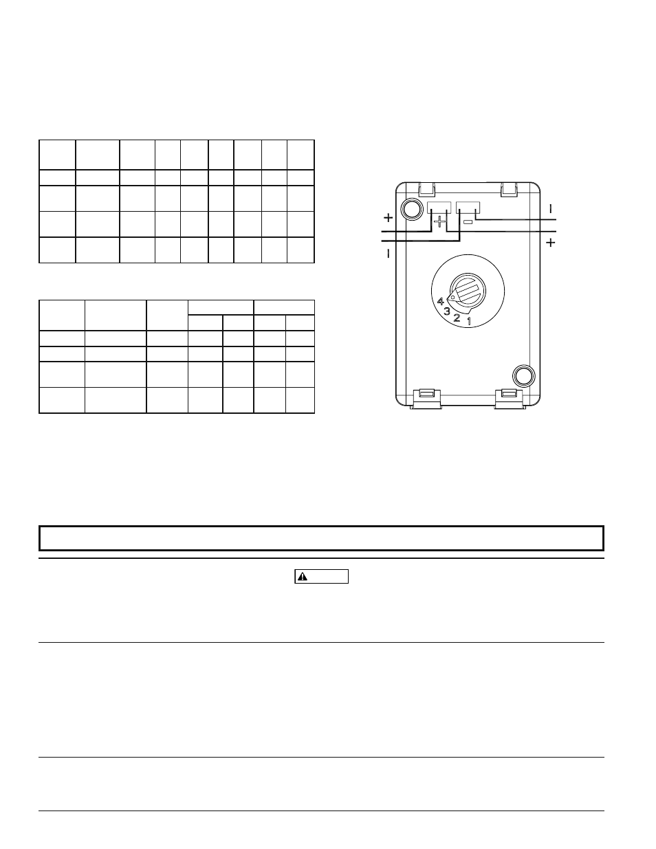
Sounder setting selection is accomplished by using the rotary switch on the
back (see Figure 3). The sound measurements for the various settings are
shown in Table 1A. The current draw for the various settings is shown in
Table 1B.
TAbLE 1A.
SOUNDER OUTpUT (dbA) REvERbERANT
SWITCH
SETTING
PATTERN
OUTPUT
LEVEL
8
VDC
8
VFWR
12
VDC
12
VFWR
16-33
VDC
16-33
VFWR
1
TEMPORAL HIGH
68
67
71
70
78
76
2
TEMPORAL
LOW
66
65
69
68
76
75
3
NON-
TEMPORAL
HIGH
72
71
75
74
80
79
4
NON-
TEMPORAL
LOW
70
69
73
72
78
77
TAbLE 1b.
SOUNDER CURRENT DRAW (mA RMS)
SWITCH
POSITION
SOUND
PATTERN
VOLUME
8-17.5 VOLTS
16-33 VOLTS
DC
FWR
DC
FWR
1
TEMPORAL
HIGH
12
10
17
15
2
TEMPORAL
LOW
10
9
14
13
3
NON-
TEMPORAL
HIGH
22
17
29
25
4
NON-
TEMPORAL
LOW
17
13
21
19
The horn will not work without power. The horn gets its power from the fire/security
panel monitoring the alarm system. If power is cut off for any reason, the horn will not
provide the desired audio or visual warning.
The horn may not be heard. The loudness of the horn meets (or exceeds) current
Underwriters Laboratories’ standards. However, the horn may not alert a sound sleeper or
one who has recently used drugs or has been drinking alcoholic beverages. The horn may
not be heard if it is placed on a different floor from the person in hazard or if placed too
far away to be heard over the ambient noise such as traffic, air conditioners, machinery
or music appliances that may prevent alert persons from hearing the alarm. The horn
may not be heard by persons who are hearing impaired.
THE LIMITATIONS Of HORNS
WARNING
THREE-yEAR LIMITED WARRANTy
System Sensor warrants its enclosed product to be free from defects in materials and
workmanship under normal use and service for a period of three years from date of
manufacture. System Sensor makes no other express warranty for this product. No agent,
representative, dealer, or employee of the Company has the authority to increase or alter
the obligations or limitations of this Warranty. The Company’s obligation of this Warranty
shall be limited to the replacement of any part of the product which is found to be defec-
tive in materials or workmanship under normal use and service during the three year
period commencing with the date of manufacture. After phoning System Sensor’s toll
free number 800-SENSOR2 (736-7672) for a Return Authorization number, send defec-
tive units postage prepaid to: System Sensor, Returns Department, RA #__________, 3825
Ohio Avenue, St. Charles, IL 60174. Please include a note describing the malfunction and
suspected cause of failure. The Company shall not be obligated to replace units which
are found to be defective because of damage, unreasonable use, modifications, or altera-
tions occurring after the date of manufacture. In no case shall the Company be liable
for any consequential or incidental damages for breach of this or any other Warranty,
expressed or implied whatsoever, even if the loss or damage is caused by the Company’s
negligence or fault. Some states do not allow the exclusion or limitation of incidental or
consequential damages, so the above limitation or exclusion may not apply to you. This
Warranty gives you specific legal rights, and you may also have other rights which vary
from state to state.
fCC STATEMENT
SpectrAlert Strobes and Horn/Strobes have been tested and found to comply with the
limits for a Class B digital device, pursuant to part 15 of the FCC Rules. These limits are
designed to provide reasonable protection against harmful interference when the equip-
ment is operated in a commercial environment. This equipment generates, uses, and
can radiate radio frequency energy and, if not installed and used in accordance with the
instruction manual, may cause harmful interference to radio communications. Operation
of this equipment in a residential area is likely to cause harmful interference in which
case the user will be required to correct the interference at his own expense.
Please refer to insert for the Limitations of Fire Alarm Systems
MOUNTING
1. The MH Mini-Horn is intended for mounting to a standard 2½˝ deep
single gang box or a standard 4 × 4 box, with single gang mud ring,
which allows sufficient clearance for conduit entrance.
2. The MH Mini-Horn is compatible with DC line supervision. The horn is
polarized and has terminals marked with polarity. Apply positive supply
voltage to the (+) terminal and negative to the (–) terminal. (See Figure 3)
3. Mount the horn to the electrical outlet box using the two mounting
screws supplied.
NOTE: SHOWN WITH CONTROL PANEL IN ALARM. PANEL POLARITY
REVERSED IN SUPERVISORY CONDITION.
TO EOL
OR
NEXT
DEVICE
FROM
CONTROL
PANEL OR
PREVIOUS
DEVICE
fIGURE 3.
A0358-00