Figure 4. wiring for coded supplies, Warning – System Sensor MDL3R and MDL3W User Manual
Page 2
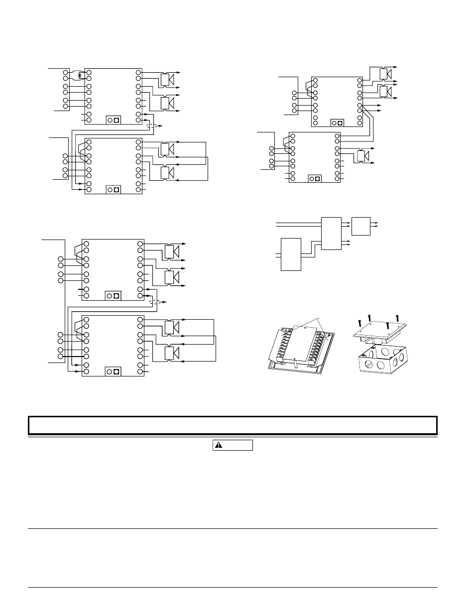
fiGURe 3. MaSteR-SLave USinG nac-SLave inpUt:
NOTE: If zone 1 is connected to synchronize other MDL3 no devices shall be
attached to this zone. Zone 1 input supply power must be continous to be
operational.
FACP
+
–
+
–
+
–
+
–
+
–
+
–
FACP
NAC 1
NAC 2
+
–
+
–
}
}
}
}
HORN
CONTROL
ZONE 1
IN
ZONE 2
IN
SLAVE
IN
+
–
+
–
+
–
+
–
}
}
}
}
ZONE 1
OUT
ZONE 2
OUT
NAC
SLAVE IN
SLAVE
OUT
TEMP JUMP OFF
+
–
+
–
+
–
+
–
}
}
}
}
HORN
CONTROL
ZONE 1
IN
ZONE 2
IN
SLAVE
IN
+
–
+
–
+
–
+
–
}
}
}
}
ZONE 1
OUT
ZONE 2
OUT
NAC
SLAVE IN
SLAVE
OUT
TEMP JUMP OFF
}
B+
B–
NAC 1
NAC 2
}
B+
B–
}
B+
B–
}
B+
B–
TO NEXT
SPECTRALERT
ADVANCE DEVICE
OR EOL (1)
TO NEXT
SPECTRALERT
ADVANCE DEVICE
OR EOL (1)
TO NEXT SPECTRALERT
ADVANCE DEVICE OR EOL (1)
2 STYLE Y ZONES
(CLASS B)
TO NEXT MDL3 NAC
SLAVE IN OR EOL (1)
MASTER
SLAVE
A0416-01
fiGURe 4. WiRinG foR coDeD SUppLieS:
HORN
POWER
STROBE
POWER
MULTI CODE
SOURCE
ANY
SPECTRALERT
HORN STROBE
TO NEXT
HORN
POWER
OR
EOL (1)
SPECTRALERT
HORN ONLY
}
TO NEXT
DEVICE
OR EOL (1)
}
MDL
HC
Z1
IN OUT
NOTE: Horn control must be powered for horn/strobes to operate the horn portion.
NOTE: SpectrAlert Advance horn-only/chime-only and horn/strobe or chime/
strobe devices must be set to coded for multi-code sourcing.
fiGUReS 5 & 6. MoUntinG DiaGRaM:
BARRIER STRIPS
1. Fold barrier strip flat and complete field wiring. Input terminal wire
gauge: 12 to 18 AWG.
2. Fold barrier strips toward terminal block and mount unit to back box with
screws provided. Back box must be 4-
11
/
16
˝ x 4-
11
/
16
˝ x 2-
1
/
8
˝ deep.
fiGURe 1. hoRnS SiLenceD oveR tWo WiRe ciRcUit:
NOTE: If zone 1 output of module is connected to strobes, chime/strobes or horn/
strobes, zone 1 input supply power must be continuous for proper operation.
FACP #1
+
–
+
–
+
–
+
–
+
–
+
–
+
–
EOL
(1)
FACP #2
NAC 1
+
–
+
–
}
}
}
}
HORN
CONTROL
ZONE 1
IN
ZONE 2
IN
SLAVE
IN
+
–
+
–
+
–
+
–
}
}
}
}
ZONE 1
OUT
ZONE 2
OUT
NAC
SLAVE IN
SLAVE
OUT
TEMP JUMP OFF
+
–
+
–
+
–
+
–
}
}
}
}
HORN
CONTROL
ZONE 1
IN
ZONE 2
IN
SLAVE
IN
+
–
+
–
+
–
+
–
}
}
}
}
ZONE 1
OUT
ZONE 2
OUT
NAC
SLAVE IN
SLAVE
OUT
TEMP JUMP OFF
}
B+
B–
NAC 1
}
B+
B–
NAC 2
}
B+
B–
NAC 3
}
B+
B–
}
A+
A–
TO NEXT
SPECTRALERT
ADVANCE DEVICE
OR EOL (1)
TO NEXT
SPECTRALERT
ADVANCE DEVICE
OR EOL (1)
TO NEXT
SPECTRALERT
ADVANCE DEVICE
TO NEXT
SPECTRALERT
ADVANCE DEVICE
WIRING MUST BE
CONTAINED WITH EITHER
THE COMMON ENCLOSURE
OF MODULES OR
ENCLOSURES WITHIN 20
FEET OF EACH OTHER WITH
WIRING INSIDE CONDUIT
STYLE Z ZONES
(CLASS A)
2 STYLE Y ZONES
(CLASS B)
MASTER MODULE HORN CONTROL CONNECTS TO INTERRUPTABLE POWER SOURCE
MASTER
SLAVE
A0414-01
fiGURe 2 MaSteR-SLave MoDe:
NOTE: If zone 1 output of module is connected to strobes, chime/strobes or horn/
strobes, zone 1 input supply power must be continuous for proper operation.
FACP
+
–
+
–
+
–
+
–
+
–
+
–
NAC 3
+
–
+
–
}
}
}
}
HORN
CONTROL
ZONE 1
IN
ZONE 2
IN
SLAVE
IN
+
–
+
–
+
–
+
–
}
}
}
}
ZONE 1
OUT
ZONE 2
OUT
NAC
SLAVE IN
SLAVE
OUT
TEMP JUMP OFF
+
–
+
–
+
–
+
–
}
}
}
}
HORN
CONTROL
ZONE 1
IN
ZONE 2
IN
SLAVE
IN
+
–
+
–
+
–
+
–
}
}
}
}
ZONE 1
OUT
ZONE 2
OUT
NAC
SLAVE IN
SLAVE
OUT
TEMP JUMP OFF
}
B+
B–
NAC 1
NAC 2
}
B+
B–
}
B+
B–
}
A+
A–
TO NEXT
SPECTRALERT
ADVANCE DEVICE
OR EOL (1)
TO NEXT
SPECTRALERT
ADVANCE DEVICE
OR EOL (1)
TO NEXT
SPECTRALERT
ADVANCE DEVICE
TO NEXT
SPECTRALERT
ADVANCE DEVICE
WIRING MUST BE
CONTAINED WITH EITHER
THE COMMON ENCLOSURE
OF MODULES OR
ENCLOSURES WITHIN 20
FEET OF EACH OTHER WITH
WIRING INSIDE CONDUIT
STYLE Z ZONES
(CLASS A)
2 STYLE Y ZONES
(CLASS B)
(STYLE Z CLASS A)
MASTER
SLAVE
SS-110-000
2 I56-3157-004R
©2012 System Sensor
thRee-yeaR LiMiteD WaRRanty
System Sensor warrants its enclosed product to be free from defects in materials and workmanship un-
der normal use and service for a period of three years from date of manufacture. System Sensor makes
no other express warranty for the enclosed product. No agent, representative, dealer, or employee of
the Company has the authority to increase or alter the obligations or limitations of this Warranty. The
Company’s obligation of this Warranty shall be limited to the replacement of any part of the product
which is found to be defective in materials or workmanship under normal use and service during the
three year period commencing with the date of manufacture. After phoning System Sensor’s toll free
number 800-SENSOR2 (736-7672) for a Return Authorization number, send defective units postage pre-
paid to: System Sensor, Returns Department, RA #__________, 3825 Ohio Avenue, St. Charles, IL 60174.
Please include a note describing the malfunction and suspected cause of failure. The Company shall not
be obligated to replace units which are found to be defective because of damage, unreasonable use,
modifications, or alterations occurring after the date of manufacture. In no case shall the Company be
liable for any consequential or incidental damages for breach of this or any other Warranty, expressed
or implied whatsoever, even if the loss or damage is caused by the Company’s negligence or fault. Some
states do not allow the exclusion or limitation of incidental or consequential damages, so the above
limitation or exclusion may not apply to you. This Warranty gives you specific legal rights, and you may
also have other rights which vary from state to state.
The sounder and/or strobe will not work without power. The sounder/strobe gets its power from the
fire/security panel monitoring the alarm system. If power is cut off for any reason, the sounder/strobe
will not provide the desired audio or visual warning.
The sounder may not be heard. The loudness of the sounder meets (or exceeds) current Underwriters
Laboratories’ standards. However, the sounder may not alert a sound sleeper or one who has recently
used drugs or has been drinking alcoholic beverages. The sounder may not be heard if it is placed on
a different floor from the person in hazard or if placed too far away to be heard over the ambient noise
such as traffic, air conditioners, machinery or music appliances that may prevent alert persons from
hearing the alarm. The sounder may not be heard by persons who are hearing impaired.
The signal strobe may not be seen. The electronic visual warning signal uses an extremely reliable
xenon flash tube. It flashes at least once every three seconds and exceeds current Underwriters
Laboratories standards for private mode viewing. The visual warning signal is suitable for direct view-
ing and must be installed within an area where it can be seen by building occupants. The strobe must
not be installed in direct sunlight or areas of high light intensity (over 60 foot candles) where the visual
flash might be disregarded or not seen. The strobe may not be seen by the visually impaired and is not
intended to meet American Disabilities Act (ADA) requirements.
The signal strobe may cause seizures. Individuals who have positive photic response to visual stimuli
with seizures, such as persons with epilepsy, should avoid prolonged exposure to environments in
which strobe signals, including this strobe, are activated.
The signal strobe cannot operate from coded power supplies. Coded power supplies produce interrupted
power. The strobe must have an uninterrupted source of dc power in order to operate correctly. System
Sensor recommends that the sounder and signal strobe always be used in combination so that the risks
from any of the above limitations are minimized.
WARNING
the LiMitationS of SoUnDeR/StRobeS
Please refer to insert for the Limitations of Fire Alarm Systems
A0415-01
A0423-00
A0265-01