Chime surface mount, Chime with universal mounting plate, Chime direct mount – System Sensor CH1224 and CH1224W Electronic Chime_Sounder User Manual
Page 3: Mounting diagrams: mounting, Figure 1
D900-00-00 3 I56-0003-004R
4-INCH BACK BOX
BBS, BBSW
A
A
LOCKING RIB SLOT
LOCKING RIB
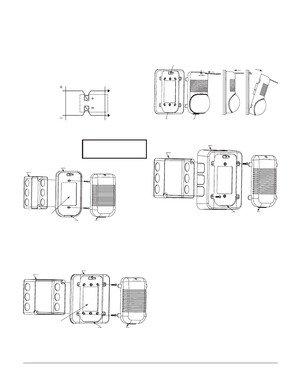
Chime surface mount:
1. Mount skirt to back box with screws A.
2. Complete field wiring.
3. Insert locking rib on unit into slot on skirt.
4. Press into skirt; unit will make a “click” when it has locked into
place.
(NOTE: Chime and skirt may also be mounted to a 2-inch box using
screws B instead of screws A.)
���������������
�����������������
�������������������
����������������
�����������
�
�
������������������������������
Chime with universal mounting plate:
1. Mount plate to back box using screws A.
2. Complete field wiring.
3. Insert locking rib into slot on plate.
4. Press into plate, unit will make a “click” when it has locked into
place.
2-INCH BACK BOX
WALL OPENING MUST
EQUAL PLATE OPENING
S-MP, S-MPW
LOCKING RIB SLOT
LOCKING RIB
B
B
Chime direct mount:
1. Mount plate to back box using screws B.
2. Break off four tabs from unit.
3. Complete field wiring.
4. Insert locking rib into slot on plate.
5. Press into plate; unit will make a “click” when it has locked into
place.
Screw types used for mounting:
A = 8-32 ×
3
⁄
4
flat head
B = 6-32 × 1
5
⁄
16
pan head
Mounting Diagrams:
Mounting
1. The chime is intended for mounting to a standard 1
1
/
2
″ deep single-
gang box which allows sufficient clearance for conduit entrance.
2. The chime is compatible with DC line supervision, is polarized, and
has terminals marked with polarity. Apply positive supply voltage to
the (+) terminal and negative supply voltage to the (–) terminal. (See
Figure 1.)
3. Mount the chime to the electrical outlet box using the two mounting
screws supplied.
4. Field repair of the chime should not be attempted. Return to factory
for repair or replacement.
NOTE: Shown with control panel in alarm. Panel polarity reversed in
supervisory condition.
Figure 1:
����
�������
�����
��
��������
�������
��
���
��
����
������
A0179-00
A0180-00
Figure 2: Removal of horns and strobes from mounting
plates:
To remove units from mounting plates, insert screwdriver as shown to
unlock snap. While pushing in screwdriver to release the snap, pull back
on the chime/sounder. Hinge the chime/sounder module, disengage the
Locking Rib, and lift the chime/sounder away from the mounting plate.
PLASTIC SNAP LEVER
TAB SLOT
TAB
INSERT REMOVAL TOOL
A0204-00
A0115-00
A0178-00