Superwinch S4000 - 1,814 kgs/12V User Manual
Page 6
Do not sub-
stitute any
strength grade weaker than
grade 5.
When attaching wires to the motor
terminals and solenoid (relay), hold
the inner nut when tightening the
outer nut. Do not allow the motor
terminals to rotate for it may cause
internal wire breakage or part mis-
alignment. Be especially careful in
preventing the solenoid (relay)
terminals from rotating. Any
rotation can damage the solenoid
(see Figure 10).
Step (3)
Disconnect the vehicle battery
leads.
Automobile
batteries
contain gasses which are flammable
and explosive. Wear eye protection
during installation and remove all
metal jewelry. Do not lean over
battery while making connections.
Step (4)
Route the two (2) wires through
the vehicle grille to the battery. To
ensure against insulation abrasion
and/or cutting, apply several layers
of electrical tape where wiring may
come in contact with sharp metal
parts of the vehicle. Attach the cir-
cuit breaker assembly to the end of
the red wire. Wrap the circuit
breaker assembly with electrical tape
to prevent accidental short circuits.
Attach other end of circuit breaker
assembly to battery positive terminal.
DANGER
!
WARNING
!
I N S TA L L AT I O N
C O N T.
11
Be Prepared
Figure 11
Figure 10
Superwinch mounting (fitting) kits
are available for most popular vehi-
cles. If you can‘t locate a kit locally
contact Superwinch at the address
listed on the front of this manual
for the name of a Superwinch dealer
near you.
Detailed Mounting instructions are
provided with each mounting kit.
Read and follow directions carefully
to ensure proper winch alignment
and trouble free operation.
This winch
MUST be mount-
ed with the wire rope in the under-
wind direction. Improper mounting
could damage your winch and void
your warranty.
MINIMUM ELECTRICAL
REQUIREMENTS
For 12 volt winches, a 60 ampere
alternator and battery with 440
cold-cranking amperes capacity are
the minimum recommended power
sources. If the winch is in heavy use,
an auxiliary battery and heavy duty
alternator are recommended.
Step (1)
Install mounting kit or structural
support for winch.
Step (2)
When mounting the winch, pull the
freespool clutch lever into the freespool
position. Unwind 25-30 feet of rope
from the drum. This will provide the
access needed to install the mounting
bolts into the base plate mounting holes.
WARNING
!
I N S TA L L AT I O N
M O U N T I N G
Y O U R W I N C H
NOTES
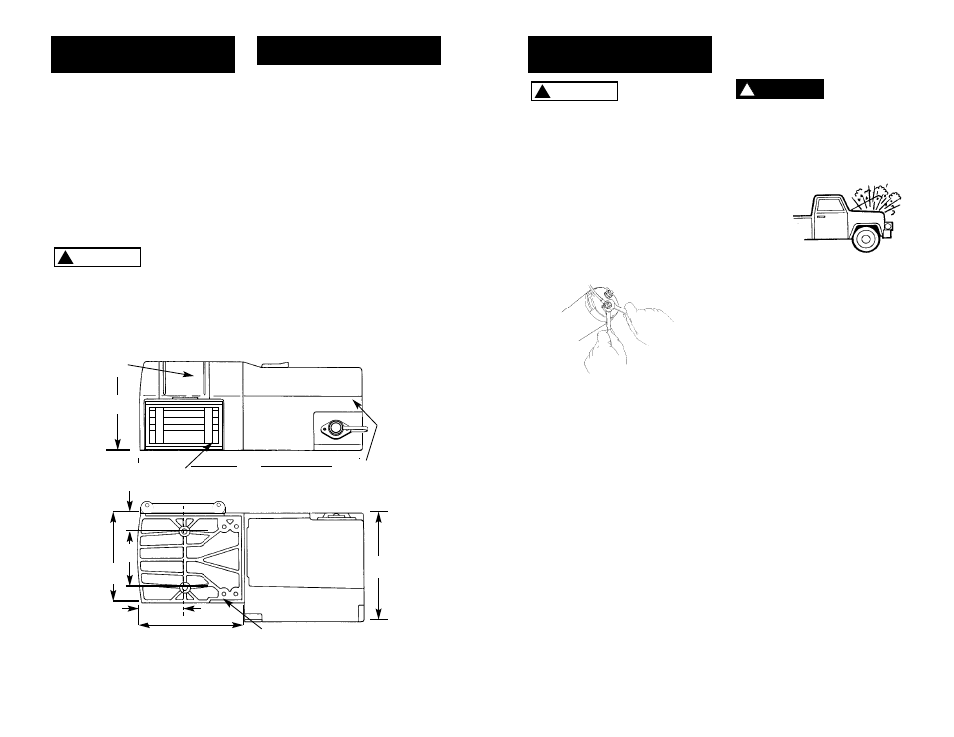
1. All dimensions are in inches [millimeters].
2. Typical mount is to flat surface capable of handling the loads. Bolts to be Grade 5 or better.
6.0
(152)
15.1
(383)
7.2
(183)
7.1
(180)
3.1
(79)
5.9
(150)
3.69
(93.7)
1.24
(31.5)
10
ROLLER FAIRLEAD
SCREWS
DRUM SUPPORT
PLATE SCREWS
MOTOR
SCREWS
DRUM SUPPORT
PLATE
Figure 9
Mount the winch to the mount that
you have designed. Mounting bolts
supplied are the
correct length for
use with up to a
1/4”(6.3 mm)
thick plate.