Maintenance, Troubleshooting, Air supply – Sunex Tools SX1819T User Manual
Page 4: Lubrication, Operation, Servicing procedures
SX1819T: Parts Breakdown & Operating Manual
4
04/19/10
3. Jaw Opening adjustment:
To obtain the maximum stroke of the tool, proper distance setting between
the jaw housing and the head is very important. First loosen the lock nut.
A rivet is then inserted into the nosepiece which should be selected to
match the rivet size to be set. While screwing or unscrewing the head to
achieve the minimum opening of the jaws, check if the rivet mandrel can
be removed and inserted freely. Fasten the lock nut after the adjustment.
Maintenance...
1. Check the tightness of the connections between the jaw housing coupler,
nut, jaw housing, and the hydraulic plunger, the nosepiece, the head and
the lock nut.
2. If the jaws show excessive wear and/or are dirty, follow the steps
provided in the servicing procedures section.
Troubleshooting...
1. Rivet mandrel is gripped by the jaws but the rivet can not be set
and mandrel can not be bro ken:
CAUSE: Low air pressure or loss of hydraulic fluid.
REMEDY: Increase air pressure to 7 bar (100 psi) maximum at tool. Make
sure all fittings including rear gland and head are tight. If malfunction
persists, call authorized Sunex Tools
®
warranty center.
2. Mandrel does not fit completely into nosepiece or fails to eject:
CAUSE: Jaw Housing distance incorrect.
REMEDY: Loosen the head and check the rated stroke length.
If shorter, search for worn or damaged O-rings and replace it.
CAUSE: Jaws are dirty or damaged.
REMEDY: Clean or replace the jaws.
CAUSE: Fatigued jaw pusher spring.
REMEDY: Replace the jaw pusher spring.
CAUSE: Fatigued Return Spring.
REMEDY: Replace the return spring.
CAUSE: Air leakage in vacuum system.
REMEDY: Search for worn or damaged seals in the vacuum system and
replace it.
3. Tool takes more than two strokes under ideal con di tions to set rivet
and break mandrel:
CAUSE: Low air pressure.
REMEDY: Increase air pressure but do NOT exceed 7 bar (100 psi)
at tool.
CAUSE: Loose Nosepiece or improper size of nose piece.
REMEDY: Tighten nosepiece or use right size.
CAUSE: Rivet body too long for the thickness of the joint.
REMEDY: The rivet body should be 3-6mm longer than the thickness of
joint only.
If malfunction persists, call an authorized Sunex Tools
®
war ran ty center.
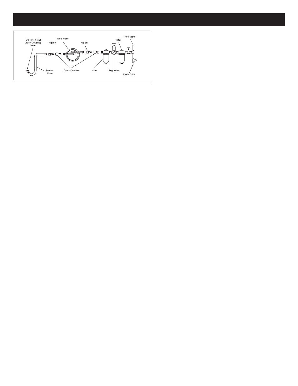
Air Supply...
Tools of this class operate on a wide range of air pres sures. It is recommended
that air pres sure of these tools mea sures 90 psi at the tool while running free.
Higher pres sure (over 90 psi; 6.2 bar) raises per for mance beyond the rated
capacity of the tool which will short en tool life be cause of faster wear and
could cause injury.
Always use clean, dry air. Dust, corrosive fumes and/or water in the air line
will cause damage to the tool. Drain the air tank daily. Clean the air inlet filter
screen on at least a weekly schedule. The rec om mend ed hookup pro ce dure can
be viewed in above figure.
The air inlet used for connecting air supply has standard 1/4" NPT. Line
pressure should be increased to compensate for unusually long air hoses (over
25 feet). Minimum hose diameter should be 3/8" I.D. and fittings should have
the same inside dimensions and be tightly secured.
Lubrication...
Lubricate the air tool with quality air tool oil. If no air line oiler is used, run 1/2
ounce of air tool oil through the tool by squirting oil into the tool's air inlet or
into the nearest connection to the air inlet, reconnecting air supply, and then
running tool. Do not use more than 1/2 ounce of oil, as overfilling will reduce
the performance of the tool.
Operation...
When the Lever/Trigger is depressed, the throttle valve is moved down off
its seat by the valve tube. Air enters the bottom of the air cylinder, forcing
the piston assembly up. As the piston assembly rises, the plunger rod forces
hydraulic fluid in to the upper part of the hydraulic section, retracting the
hydraulic plunger. Meanwhile, the jaws grip the mandrel of the rivet, pulling
until the rivet is set and breaking the mandrel in the process.
When the lever is released, the throttle valve resets and shuts off the air supply.
The valve tube spring then lifts the valve tube and exhausts the air throughout
the hollow of the valve tube. The return spring returns the hydraulic plunger to
its original position. This opens the jaws, releases the mandrel, and retracts the
piston assembly back to its original static site.
Servicing Procedures...
1. Changing Nosepieces:
Hook up the tool to the air line and depress the lever. While continuing to hold
the lever down, use the maintenance tool to remove the unwanted nosepiece
and tighten the new nosepiece in place again. When the lever is released and
the tool is at rest, a circular opening should be visible when looking through
the hydraulic section from the rear gland to the nosepiece.
2. Cleaning and Changing of the Jaws:
Disconnect the tool from the air line and then remove the head with the
maintenance tool. Hold the jaw housing coupler firmly and remove the jaw
housing. Clean the jaws with either a steel brush or solvent. If excessive
wear is apparent, replace them with new jaws. Before reassembling, apply a
thin coat of oil to the sliding surface of the jaws. Reassemble the tool in the
reverse order while making sure that the chamfered end of the jaw pusher is
in contact with the jaws properly.
Operating Instructions • Warning Information • Parts Break down