Solar, Panel installation, Connect solar panel(s) to operator control box – LiftMaster LA412 Solar Powered Residential Gate Operator User Manual
Page 29: Connect batteries
28
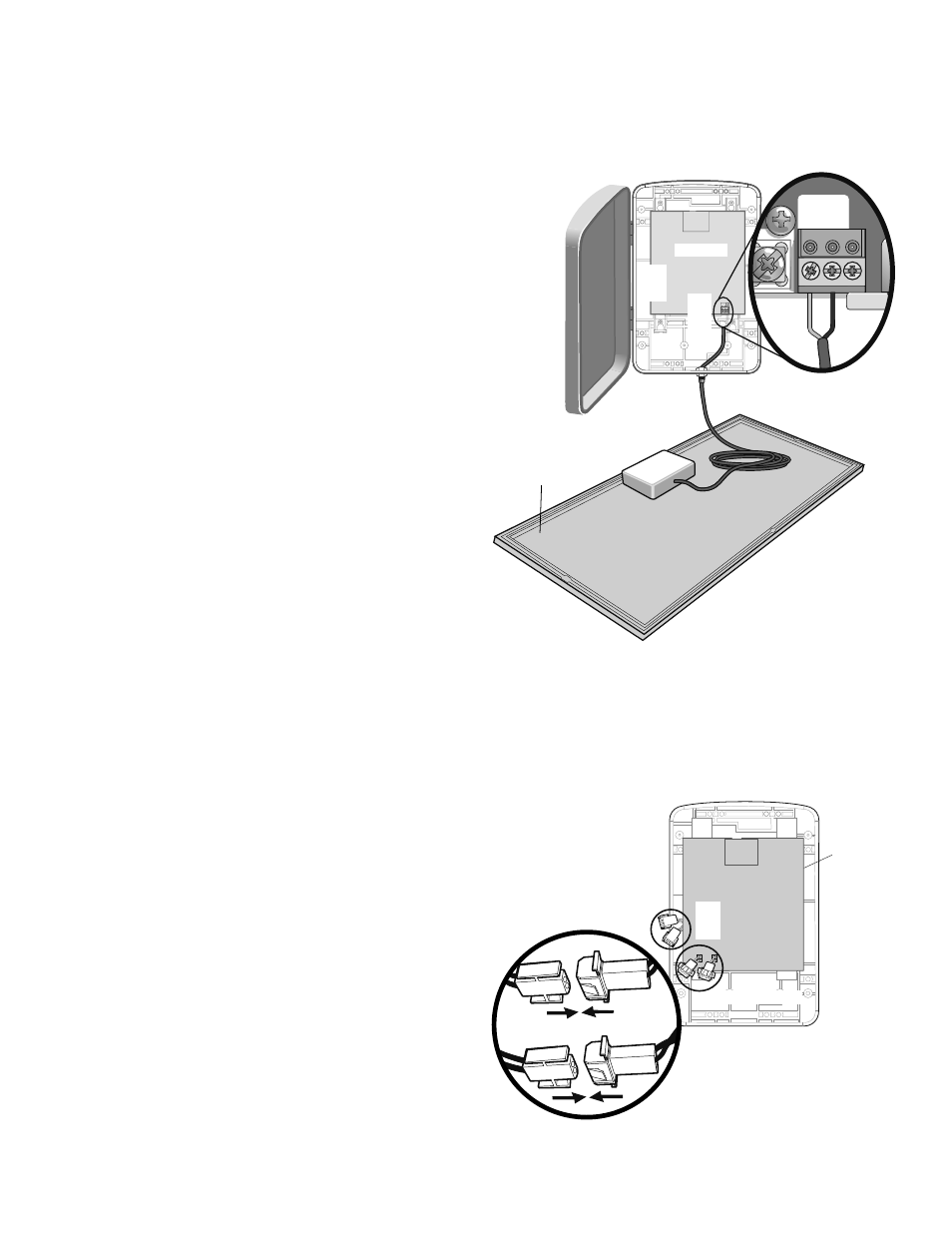
CONNECT SOLAR PANEL(S) TO OPERATOR
CONTROL BOX
Open the control box cover.
Disconnect all power and batteries from the control board.
Run the solar panel cable to the bottom of the control box. Thread the cable
through the watertight connector and pull the cable through until it reaches the
AC PWR/SOLAR connector on the control board.
Tighten the watertight connector on the cable.
Attach the solar panel wires to AC PWR/SOLAR input terminal (polarity is
not important). Leave the AC PWR/SOLAR earth ground connection open.
With the batteries still disconnected, the control board should power up if the
solar panel is correctly installed and the sun is shining (the diagnostic LED will
blink).
NOTE: The system is designed to be charged by either an AC plug-in transformer or
a separate solar panel, but not both.
Use the cable ties to secure the solar panel cable away from places where it
could be damaged.
NOTE: If the sky is too overcast to allow the solar panel to power up the system,
the panel will need to be verified at another time when the sun is shining. There is no
other way to verify the panel installation.
AC PWR/
SOLAR
J4
Control Board
Black
Red
Solar Panel
SOLAR
PANEL INSTALLATION
» CONNECT SOLAR PANEL(S) TO OPERATOR CONTROL BOX
+ CONNECT BATTERIES
1
2
3
4
5
6
CONNECT BATTERIES
The batteries are charged in circuit by using the solar panel (provided).
Locate the two white battery plugs on the left-hand side of the control box.
Connect the plug from the battery to connector on the control board.
NOTES: Batteries will degrade over time depending on temperature and usage. For
best performance, the batteries should be replaced every 3 years. Batteries do not
perform well in extremely cold temperatures.
3 3
Ø
A 32VA 32V
Control Board
Board Connectors
Battery Connectors
18
R93
L1
D42
K2
D1Ø
Z22
P1
F2
MO
V1
D1
Q12
U4
OFF
MAX
OPEN
SINGLE BUTTON
RESET
STOP
CHGR
OVLD
COM
COM
D129
Z4
U3
D2
D44
C11
C13
C12
D16
F9
R1Ø1
R1ØØ
K1
Q22
F3
K3
K4
R196
F1
Z12
GATE 2
GATE 1
MAGR
SOL
GR
WH
YL
BL
RD
BR
GR
WH
YL
BL
RD
BR
F7
24V
CTRL
OVLD
TIMER
RUNNING
GATE 2
SET
OPEN
LIMIT
SET
CLOSE
LIMIT
LEARN
LIMITS
GATE 1
LEARN
XMITTER
LOCK /
ON
OFF
C69
OFF
MAX
J2
Ø
PWR
AC PWR
/SOLAR
D8
D4
R9
R329
R27
MO
V2
R4
C2
BIPART DELAY
LOCK
GND
Z1
R1
R2
K5
F12
Q9
R9Ø
F8
Q6
Q1
J19
R182
C1Ø1
C75
C73
C72
C71
C7Ø
C66
C65
C68
C33
F11
R186
R42Ø
R423
J24 J
23 3
Ø
A 32V
3
Ø
A 32V
J21
30
30
C64
R22
U2
J18
K6
JU1
JU1
JU2
DB1
D36
R184
Battery Connection
1
1
2
2
1
2
3
4
5
6