Harrington Hoists and Cranes SMR Trolley User Manual
Page 14
14
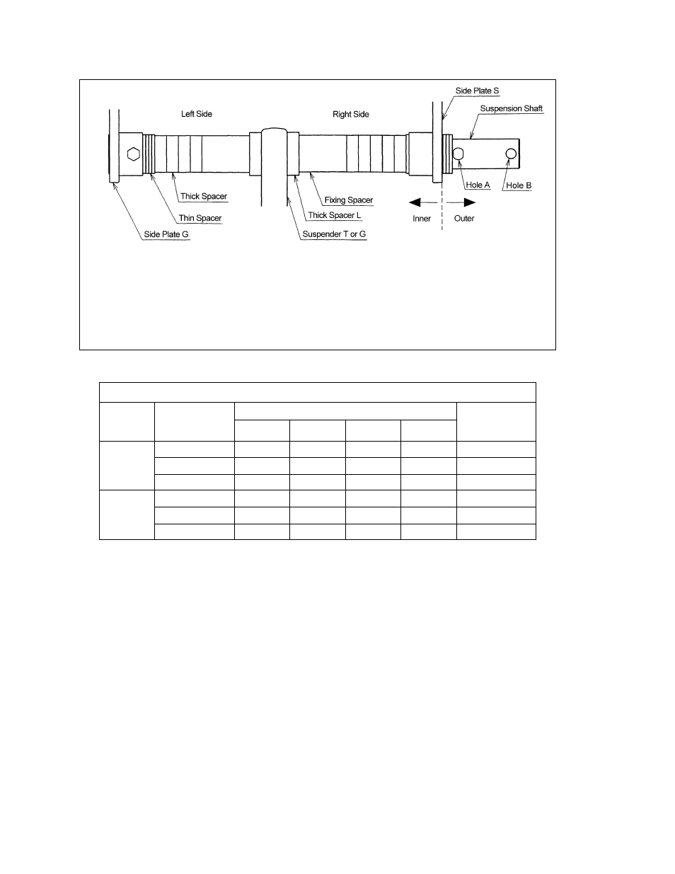
Note: Inner Spacer rows on Table 3-2 list two numbers. First number is the quantity of spacers located on the
left side of the Suspender or Suspension Plates, second number is the quantity on the right side.
Example: 1 + 2
ç Adjusting Spacers on the right side (Side Plate S side)
é Adjusting Spacers on the left side (Side Plate G side)
Figure 3-8
Spacers Arrangement
Table 3-1
Suspension Shaft Adjusting Spacers, and Suspension Shaft Bolt
Total Number of Spacers Supplied
Capacity
(Tons)
Flange Range
(in)
Thin
Thick
Fixing
Thick L
Suspension
Shaft Bolt
Location
2.28 to 5.00
8
3
2
Hole 2
5.01 to 6.02
8
5
2
Hole 1
1
6.03 to 12.00
8
9
2
2
Hole 1
3.23 to 6.02
8
3
2
Hole 2
6.03 to 7.02
8
5
2
Hole 1
2 & 3
7.03 to 12.00
8
9
2
2
Hole 1
See also other documents in the category Harrington Hoists and Cranes Hoist:
- LB Lever Hoist - (L5) (64 pages)
- LX Mini Lever Hoist (6 pages)
- CF Hand Chain Hoist (48 pages)
- CB Hand Chain Hoist (56 pages)
- CX Hand Chain Hoist (6 pages)
- (N)ER Hoist - ((N)ER2) (96 pages)
- (N)ER Large Cap Hoist - ((N)ER2 (60 pages)
- ED Hoist - (ED3) (52 pages)
- ED 1050 Supplement - (ED3) (20 pages)
- (N)ERCC Hoist - ((N)ER2) (12 pages)
- (N)ER Load Limiter - ((N)ER2) (36 pages)
- SNER Hoist (64 pages)
- Food Grade Supplement (ER2/MR2/PT) (64 pages)
- NER2 Smart Limits Supplement (20 pages)
- TNER Theater Hoist (56 pages)
- (N)ER Hoist - ((N)ER1) (72 pages)
- ER Large Capaciy Hoist - (ER1) (54 pages)
- (N)ERCC Hoist - ((N)ER1) (12 pages)
- (N)ER Load Limiter - ((N)ER1) (23 pages)
- SH Hoist (9 pages)
- PT Trolley (80 pages)
- (G)NTH Trolley (58 pages)
- MR Trolley - (MR2) (76 pages)
- MCR Trolley (52 pages)
- SHB Trolley (44 pages)
- MR Trolley - (MR1) (66 pages)
- TCR Hoist - (1/4-6 Ton) (72 pages)
- TCS Hoist (52 pages)
- TCR Large Cap - (10-25 Ton) (54 pages)
- AH Hoist (56 pages)
- RH - Advantage Wire Rope Hoist (64 pages)
- RH Wire Rope Hoist (68 pages)
- RHN - Rhino Wire Rope Hoist (112 pages)
- Series 3 End Truck (80 pages)
- HPC 500 End Truck (32 pages)
- Static/Dynamic Hoist Load Tester (34 pages)
- UBC-Universal Beam Clamp (8 pages)
- HSC Sling Chain (8 pages)