Harrington Hoists and Cranes SMR Trolley User Manual
Page 13
13
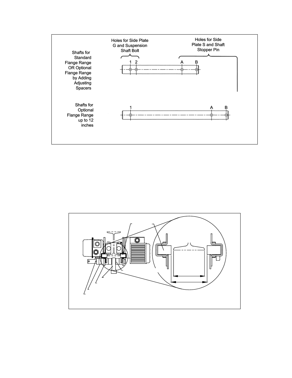
Figure 3-5
Suspension Shafts
3.1.6
Adjusting the trolley width - After assembling trolley per
Section 3.1.5
, check the adjustment as follows:
1)
Refer to
Figure 3-6
.
2)
Make sure both side plates are spread fully outward and Measure Dimension "A". Dimension "A"
must be 1/8 to 3/16" greater than "B". For trolleys up through 3 Ton.
3)
If "A" does not fall within the specified range, move spacers from inner to outer or from outer to
inner as necessary to obtain the proper "A" dimension, irrespective of the numbers in
Table 3-2
.
4)
After obtaining the proper adjustment, install the Shaft Stopper Pin in Hole A, insert the Split Pin
into the Shaft Stopper Pin, and securely bend both branches of the split pin.
B
A
Shaft Stopper Pin
Suspender
Outer Adjusting Spacers
Inner Adjusting Spacers
Side Plate S
Side Roller
Flange
Figure 3-6
Adjusting the Trolley – Up Through 3 Ton Capacity