Gilderfluke&Co Frequency Shift Keyed/Remote Terminal Unit User Manual
Page 7
for transmitting a checksum. The FSK/RTU can use this to verify that the data received from
PC•MACs has no transmission errors in it. If you address a FSK/RTU or other DMX-512 device to
addresses 256 or 257, you will see this verification data displayed as a flickering pattern. Note
that at frame rates higher than 40 FPS, not all 256 channels will be transmitted through the
DMX-512 output.
The positive and negative DMX-512 wires are attached to the FSK/RTU through the screw
terminals marked on its back. The shield (if any) can be attached to the ground side of the
power supply terminal.
E) Four J-6 connectors for Digital Data Output:
In all the animation systems made by
Gilderfluke & Company, all digital input and output cabling is through what we call ‘J6’ stan-
dard output cables. These are 40 wire cables which are made up of four identical eight bit
wide ‘channels’. A J6 cable is often split up into four individual channels. Each ‘1/4 J6’ cable is
made up of 10 wires, and can be used to control eight individual ‘digital’ (off/on) devices, or
one eight bit wide ‘analog’ device. The remaining two wires in each 1/4 J6 are used for
ground and a power connection.
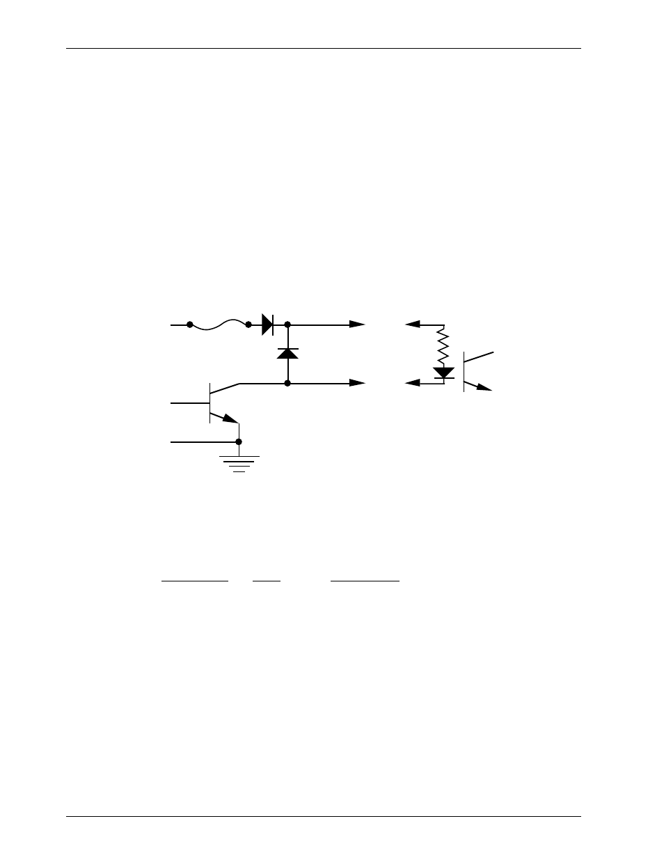
In all the animation systems made by Gilderfluke & Company, all digital outputs are open
collector switches to ground, and all digital inputs are through optoisolators. Flyback diodes
are included in the outputs for driving inductive loads:
typical output
typical input
fuse
flyback
diode
supply
supply
To simplify wiring to any of our animation systems, the connectors used on the J6 cables
are what are called ‘insulation displacement connectors’. These simply snap on to an entire
cable, automatically ‘displacing’ the wire insulation and making contact with the wires within.
This means that an entire 40 wire cable can be terminated in seconds. All connectors are po-
larized, to keep them from being plugged in backwards.
Each J6 cable is arranged in the following order:
wire number
color
wire function
1
brown
circuit ground
2
red
channel 0 data bit 7
3
orange
channel 0 data bit 6
4
yellow
channel 0 data bit 5
5
green
channel 0 data bit 4
6
blue
channel 0 data bit 3
7
violet
channel 0 data bit 2
8
gray
channel 0 data bit 1
9
white
channel 0 data bit 0
10
black
+ unregulated power supply (protected to 1 amp)
11
brown
circuit ground
12
red
channel 1 data bit 7
13
orange
channel 1 data bit 6
14
yellow
channel 1 data bit 5
15
green
channel 1 data bit 4
16
blue
channel 1 data bit 3
G
ILDERFLUKE
& C
O
. • 205 S
OUTH
F
LOWER
S
T
. • B
URBANK
, C
ALIF
. 91502-2102 • 818/840-9484 •
FAX
818/840-9485
3 of 25