8 of 12 – Gilderfluke&Co Z-Brick User Manual
Page 12
24
yellow
channel 2 data bit 5
25
green
channel 2 data bit 4
26
blue
channel 2 data bit 3
27
violet
channel 2 data bit 2
28
gray
channel 2 data bit 1
29
white
channel 2 data bit 0
30
black
unregulated power supply (PTC fused for 1 amp)
31
brown
circuit ground
32
red
channel 3 data bit 7
33
orange
channel 3 data bit 6
34
yellow
channel 3 data bit 5
35
green
channel 3 data bit 4
36
blue
channel 3 data bit 3
37
violet
channel 3 data bit 2
38
gray
channel 3 data bit 1
39
white
channel 3 data bit 0
40
black
unregulated power supply (PTC fused for 1 amp)
Any eight digital devices or one eight bit analog device can be con-
nected to any 1/4 J-6 cable as shown. The LED between the ground (pin
#1 brown) wire and supply (pin #10 black) wire acts as an indicator which
is lit if the fuse for that channel is OK:
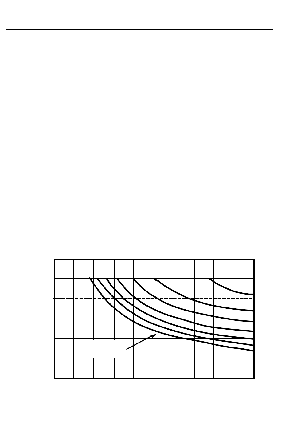
The current Output Capacity of a each output is as shown in the follow-
ing chart:
400ma.
600ma.
500ma.
300ma.
200ma.
100ma.
2
3
4
5
8
7
6
Output Duty Cycle
Allowable Peak Collector Current @
70ºC
Peak Collector Current as a function
of Output Duty Cycle
10%
20%
30%
40%
50%
60%
70%
80%
90%
100%
Number of outputs
conducting
simultaneously
G
ILDERFLUKE
& C
O
.• 205 S
OUTH
F
LOWER
S
TREET
• B
URBANK
, C
ALIFORNIA
91502 • 818/840-9484 • 800/776-5972 •
FAX
818/840-9485
E
AST
C
OAST
/F
LORIDA
O
FFICE
• 7041 G
RAND
N
ATIONAL
D
RIVE
• S
UITE
128d • O
RLANDO
, F
L
. 32819 • 407/354-5954 •
FAX
407/354-5955
8 of 12