7 of 12 – Gilderfluke&Co Z-Brick User Manual
Page 11
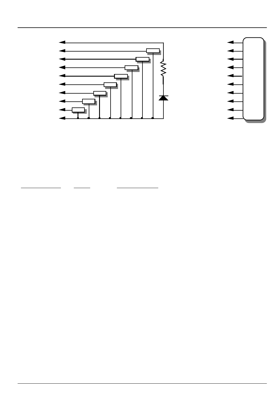
#1 ground (brown)--
#2 bit 7 (red)--
#3 bit 6 (orange)--
#4 bit 5 (yellow)--
#5 bit 4 (green)--
#6 bit 3 (blue)--
#7 bit 2 (violet)--
#8 bit 1 (grey)--
#9 bit 0 (white)--
#10 supply (black)--
load
load
load
load
load
load
load
load
#1 ground (brown)--
#2 bit 7 (red)--
#3 bit 6 (orange)--
#4 bit 5 (yellow)--
#5 bit 4 (green)--
#6 bit 3 (blue)--
#7 bit 2 (violet)--
#8 bit 1 (grey)--
#9 bit 0 (white)--
#10 supply (black)--
any
eight bit
analog
device
LED
2.2 K ohm
1/4 watt resistor
The supply line for each 1/4 J-6 is PTC fused for 1 amp. You should treat
each 1/4 J-6 as an individual, and not cross the outputs or supply lines from
one channel to the lines from any other channel. Doing this won’t cause
any damage, but can reduce the protection for the outputs that the fuses
normally provide.
Each J-6 cable is arranged in the following order:
wire number
color
wire function
1
brown
circuit ground
2
red
channel 0 data bit 7
3
orange
channel 0 data bit 6
4
yellow
channel 0 data bit 5
5
green
channel 0 data bit 4
6
blue
channel 0 data bit 3
7
violet
channel 0 data bit 2
8
gray
channel 0 data bit 1
9
white
channel 0 data bit 0
10
black
unregulated power supply (PTC fused for 1 amp)
11
brown
circuit ground
12
red
channel 1 data bit 7
13
orange
channel 1 data bit 6
14
yellow
channel 1 data bit 5
15
green
channel 1 data bit 4
16
blue
channel 1 data bit 3
17
violet
channel 1 data bit 2
18
gray
channel 1 data bit 1
19
white
channel 1 data bit 0
20
black
unregulated power supply (PTC fused for 1 amp)
21
brown
circuit ground
22
red
channel 2 data bit 7
23
orange
channel 2 data bit 6
G
ILDERFLUKE
& C
O
.• 205 S
OUTH
F
LOWER
S
TREET
• B
URBANK
, C
ALIFORNIA
91502 • 818/840-9484 • 800/776-5972 •
FAX
818/840-9485
E
AST
C
OAST
/F
LORIDA
O
FFICE
• 7041 G
RAND
N
ATIONAL
D
RIVE
• S
UITE
128d • O
RLANDO
, F
L
. 32819 • 407/354-5954 •
FAX
407/354-5955
7 of 12