Digital outputs, Br-minibrick8 – Gilderfluke&Co Br-miniBrick8 User Manual
Page 14
on the wires to determine the proper orientation for these connectors: The ʻ-ʼ wire is
usually brown or black. Note that most ServoMotors wonʼt be damaged by temporarily
being plugged in with the wrong orientation.
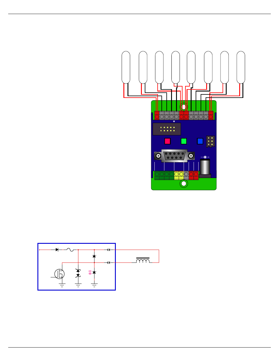
Digital Outputs:
Each Br-miniBrick8 has eight
digital outputs (hence, the name).
You can connect eight things to
the Br-MiniBrick8. These can be
LEDs, small motors, Solenoid
valves, relays, small lamps, or
anything else that needs 9 to 24
VDC, at less than 1/2 amp peak.
The outputs are just like the
standard outputs used on all Gilderfluke &
Company Show Control Systems. We switch
the negative sides of the outputs. You connect
the positive sides (usually the red wires) of the
eight things you controlling to either of the four
positive ʻcommonʼ terminals. The ʻnegativeʼ
sides of the eight things you are controlling
(usually the black wires) are connected indi-
vidually to the eight outputs. These are num-
bered 0 through 7.
There is no ʻgroundʼ screw terminal on the
output ʻendʼ of the Br-miniBrick8. You can
pick up the ground at the power supply con-
nection if needed.
The output connections for all Gilderfluke & Company Show Control Systems is
through ʻJ-6ʼ output cables. These are forty wire ribbon cables which are made up of
four identical eight bit wide ʻchannelsʼ. A J-6 cable is often split up into four individual
channels. Each ʻ1/4 J-6ʼ ribbon cable is made up of ten wires, and can be used to con-
trol eight individual ʻdigitalʼ (off/on) devices, or one eight bit wide ʻanalogʼ device. This is
what is found on a Br-miniBrick8
in addition to the screw terminal
connectors. Each group of ten
wires also includes a common
power supply and ground wire.
To s i m p l i f y w i r i n g t o a n y
Gilderfluke & Company anima-
tion system, the connectors used
on the 1/4 J-6 cables are what
are called ʻinsulation displace-
mentʼ (IDS) connectors. These simply snap on to an entire cable, automatically ʻdisplac-
ingʼ the wire insulation and making contact with the wires within. This means that an en-
tire ten wire cable can be terminated in seconds. All connectors are polarized, to keep
them from being plugged in backwards. Although there are tools made specifically for
installing these connectors, the tool we find works best is a small bench vise.
Each 1/4 J-6 cable is arranged in the following order:
MiniBrick8
Input 'A'
or 'B'
Self-Protecting
MOSFET
-
+
PTC Fuse
Relay/Solenoid
Output
Positive Common
9 to 24 vdc
Gilderfluke & Co.• 205 South Flower Street • Burbank, California 91502 • 818/840-9484 • 800/776-5972 • fax 818/840-9485
Br-miniBrick8 v3.+ Manual / 8/17/12 / page 8 of 36
0
+
1
2
3
+
+
4
5
6
7
+
+
-
S
Record
RS-232
1/4 J6
Go
Data
Trigger
A
Trigger
B
DMX
-
512
-
in
+
S
e
rv
o
P
o
w
e
r
G
ro
u
n
d
9
-
24
vdc
9–24 vdc
1 2
Servos
Outputs
Br-miniBrick8
Gilderfluke & Company
Burbank, California
Re
la
y o
r S
ole
no
id
va
lv
e c
oil
s
Re
la
y o
r S
ole
no
id
va
lv
e c
oil
s
Re
la
y o
r S
ole
no
id
va
lv
e c
oil
s
Re
la
y o
r S
ole
no
id
va
lv
e c
oil
s
Re
la
y o
r S
ole
no
id
va
lv
e c
oil
s
Re
la
y o
r S
ole
no
id
va
lv
e c
oil
s
Re
la
y o
r S
ole
no
id
va
lv
e c
oil
s
Re
la
y o
r S
ole
no
id
va
lv
e c
oil
s