Trigger input, Power supply, Digital outputs – Gilderfluke&Co Br-miniBrick4 User Manual
Page 7: Br-minibrick4
There is a trick to plugging the serial adapter to the Br-miniBrick4. The connector
must be angled towards the Br-miniBrick4 until the pins are inserted into the three
holes at the edge of the Br-miniBrick4. It is then straightened up to a right angle to the
Br-miniBrick4 to latch the connector in place.
For instructions on programming the Br-miniBrick4 using our PC•MACs software,
please refer to the Br-miniBrick8 manual. PC•MACs software programming on the Br-
miniBrick4 and the Br-miniBrick8 are identical.
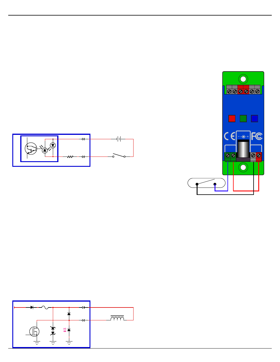
Trigger Input:
The trigger input can be used to start, stop, pause or select specific show
sequences to play from any switch. This can be a pushbutton, motion detec-
tor, IR beam, step mat, or anything else that will give you a ʻswitch closureʼ.
The trigger input is non-polarized and optoisolated. You must feed a voltage
in to trigger it. The green LED lights when a trigger input is active.
When programmed from PC•MACs, any event can be triggered on either
the ʻclosingʼ or ʻopeningʼ edge of the input. A ʻclosingʼ is when you apply a
voltage to an input. An ʻopen-
ingʼ is when that voltage is re-
moved. The inputs can be trig-
gered on any voltage from 9 to
24 VDC. If you donʼt have an
external source of power for
this inputs, you can ʻborrowʼ
some juice from
the Br-miniBrick4ʼs power supply connections (as shown).
Power Supply:
The Br-MiniBrick4 will run on any voltage from 9 through 24
VDC. Whatever voltage you use will also be used to run the relays, valves and whatever
you will be controlling. If you are controlling 24 VDC loads, you will want to use a 24
VDC power supply. For 12 volt loads, use a 12 VDC supply. The Br-MiniBrick4 itself
uses very little current. Size your power supply so it will provide enough current to run
all of your loads.
You can supply the power to the Br-miniBrick4 through the 2.1 mm power jack, or
through the screw terminals. These connections are paralleled internally.
The power supply connection is protected from reverse polarity connections. An idle
Br-miniBrick4 draws only about twenty-five milliamperes. It can run for days on just a
single nine volt battery. The loads that the Br-miniBrick4 is controlling will usually draw
far more current than the Br-miniBrick4 itself.
Digital Outputs:
Each Br-miniBrick4 has four digital outputs (hence, the name). You can connect
four things to the Br-MiniBrick4. These can
be LEDs, small motors, Solenoid valves,
relays, small lamps, or anything else that
needs 9 to 24 VDC, at (or below) the rated
current output.
The outputs are just like the standard out-
puts used on all Gilderfluke & Company
Show Control Systems. We switch the
Gilderfluke & Co.• 205 South Flower Street • Burbank, California 91502 • 818/840-9484 • 800/776-5972 • fax 818/840-9485
Br-miniBrick4 v1.1+ Manual / 8/17/12 / page 4 of 9
0
1
2
3
+
+
Record
Go
Data
Trigger
Input
-
+
Outputs
9-24 vdc
9-24 vdc
Br-miniBrick4
Gilderfluke & Company
B u r b a n k , C a l i f o r n i a
S
witch
Input 'A'
or 'B'
Self-Protecting
MOSFET
MiniBrick4
-
+
PTC Fuse
Relay/Solenoid
Output
Positive Common
9 to 24 vdc
Battery or Power Supply
Input 'A'
or 'B'
MiniBrick4
2.2 KΩ
Switch or Button
+
-
9 to 24 VDC
-
+
OptoIsolator