Securitron AQU128B User Manual
Page 5
Page 5
P/N 500-30045
Rev. A, 04/13
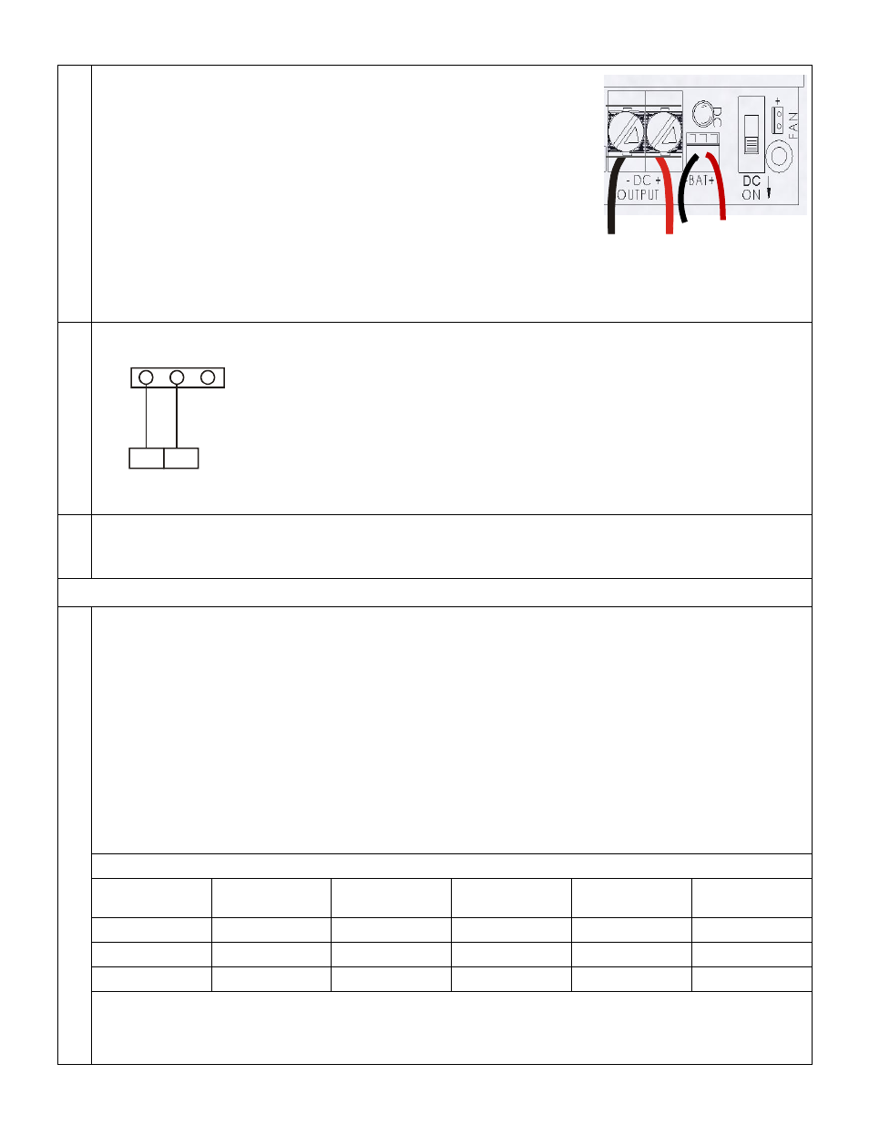
5. Make DC Power Output Connections to Devices
Using 10AWG to 24 AWG wire, connect the device wire run to the
DC outputs. Maintain separation from battery cable placement by
passing wires under power module before connecting to terminal
screws.
Connect the Positive wire to DC OUT Positive (+) terminal
Connect the Negative wire to DC OUT Negative (-) terminal
NOTE: Use appropriate wire gauge for the Amperage and
distance of the run. For more info, see Wire Loss Calculator
at http://www.securitypower.com/AN2Wire.html
6. Wiring for Status Monitoring Options
The diagram shows basic wiring to provide output to a control panel or local alarm
for notification of over-voltage or under-voltage.
AC-ON state energized the NO/C switch.
The Switch changes state when voltage exceeds 14.1 VDC or falls below 12.1 VDC
including voltage drop resulting from low battery power.
8. Turn on AC Power
After making electric connections, turn on AC power before installing batteries. The AC LED power indicator
should be lit.
C. Install Batteries
1. Understanding Battery Charging and Backup Power
The AQU128B is a backup battery charger with automatic fail over to battery power in case of primary AC
power failure when batteries are installed and connected to the power module. The use of battery backup is
optional - the unit will function without batteries installed, but no internal backup power will be available in
case of AC power failure.
Note: The battery circuit features automatic disconnect when the battery output falls to 9.9 VDC to
prevent deep discharge and also protects the power module in case the battery is connection is reversed.
For battery backup in 12VDC operation, a single 12V battery may be used, or two (2) 12V batteries may be
used wired in parallel for longer run time.
Backup power run time depends on the continuous output needed to support the load and the ambient
temperature at the enclosure. Estimates are provided in the table below:
Estimated Standby Time (3 amp/5 minute reserve for alarm)
Total Output
Amps
4Ah Battery
Standby
7Ah Battery
Standby
12Ah Battery
Standby
24Ah
Standby
40Ah
Standby
6A
.27 Hrs
.49 Hrs
.96 Hrs
2.4 Hrs
4.75 Hrs
7A
.23 Hrs
.42 Hrs
.83 Hrs
1.9 Hrs
3.8 Hrs
8A
.2 Hrs
.4 Hrs
.65 Hrs
1.6 Hrs
3.5 Hrs
Larger batteries may be used external to the enclosure by running the battery cable through a dedicated
knockout separate from the AC input and DC output.
Charge current is not less than 2A @12VDC at peak load.
Negative
+/Positive
-/Negative
NO
C NC
Trouble
Access Control
System Panel