Securitron PDD-8C8R User Manual
Securitron Power suppliers
PDD-8C8R Access Control with EOL Fire Interface Installation Instruction
Securitron Magnalock Corporation
10027 S. 51
st
St., Ste. 102
Phoenix, AZ 85044
Doc.#500-33055 Rev. A specifications subject to change without notice
ASSA ABLOY, the global leader
in door opening solutions.
Phone: (800) MAGLOCK
www.Securitron.com
Page 1 of 3
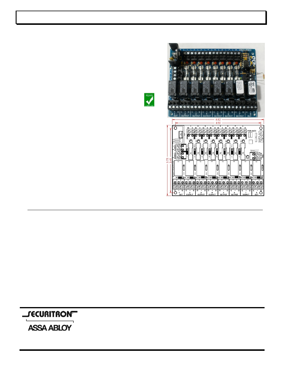
PDD-8C8R Power Distribution for Access Control with Fire Interface module
Controls and Distributes Power with 8 Control Relays with an EOL Fire trigger Interface
Power Interface for Access Control, CCTV, Fire, HVAC, Elevator,
and general low voltage system control
Features:
8 Heavy duty Relays with individual Inputs and Status LED’s
Each Relay Input can be Activated from Low Current Open
Collector, Normally Closed or Normally Open Switch
EOL End of Line Resistor Fire Interface Master Trigger de-
energizes all Output Relays that are Enabled
Universal 11 – 27.5Vdc power input
Available with PTC Circuit Breakers
Note: Only the 500mA fuse version of the board has been
evaluated by UL
Note: The outputs of the PDD-8C8R are power limited when
connected to the AQU243 power-Limited power supply
Each Output may be Individually Configured for:
o
Fire Trigger (FT) Enabled or (FTD) Disabled
o
N/O or N/C Option Configures the Relay Switched
Output
Each Output 1-8 has a protected, continuous Output and a
Relay controlled Output
TRG LED Green Indicates Trigger Status
Control Power and Main Lock Power may be Isolated
(Separate Power Supplies) at Users Option
Note: Dual/separate power source configuration has not been
evaluated by UL and cannot be configured for UL Listed
products
All Terminal Blocks are Pluggable by Channel & Function
Made in the USA with a Lifetime Warranty
Description / Instructions
The PDB-8C8R is a versatile, compact way to distribute
and control power for Access Control Systems with Fire
Alarm Interface. The PDB-8C8R is an 8 position power
distribution board with individual Relays with input (IN)
control for each output (OUT). An EOL resistor trigger
input (TRIG), will force all output relays to de-energize that
are selected (FT). In a typical installation, the TRIG would
be connected to a Fire Alarm panel via a set of contacts.
When the Fire Alarm trips, all enabled relays would be
forced to be de-energized to unlock electric doors, shut
down air systems, and or return elevators to ground floor.
Input / Output Terminals, Jumpers and LED
Details and Specifications
Control Power (- CONTR +) Two position un-pluggable
terminal block is used to power the coils of the relays. The
control voltage must be between 11 and 27.5 Vdc. Each
relay energized will draw 20ma of current. By default,
Control Power and Main Power are connected together
with jumpers J1 & J2 so no connection would be made here
unless you were using Dual/separate power as described
below. Note Dual/separate power source configuration has
not been evaluated by UL and cannot be configured for UL
Listed products.
Main Power (- POWER +) Two position un-pluggable
terminal block provides the power to the outputs to be
distributed and power to Control through J1 & J2. In a
normal application the Power must be between 11 and 27.5
Vdc and would be connected here.
Dual/Separate Power J1 & J2 Jumpers Note
Dual/separate power source configuration has not been
evaluated by UL and cannot be configured for UL Listed
products. J1 Connects (-) Power to (-) Control, J2
Connects (+) Power to (+) Control. By default J1 & J2 are
connected together. When J1 & J2 are cut, you must
supply 11 to 27.5Vdc to Control power, then you may