Securitron BPS-24-2, 3, 4, 6 AND 10 User Manual
Page 4
PN# 500-10300
Page 4
Rev. D, 04/11
AC FUSE
DC FUSE
POLYSWITCH
AUTO SHUTOFF
WITHOUT
BATTERIES
Will trip only if
internal
transformer
shorts (all LED’s
will be out)
Generally will not
trip. Supply will
go into auto
shut-off in case
of overload (all
LED’s will be out)
Generally will not
trip. Supply will
go into auto shut-
off in case of
overload* (all
LED’s will be out).
Will generally occur
in the case of any
short or overload
(all LED’s will be
out)
WITH
BATTERIES
Will trip only if
internal
transformer
shorts (all LED’s
will be out)
Will trip if
terminal F1, F2
or H shorts to
negative or in
case of overload
when terminal H
is used as single
output (all LED’s
will be out)
Will trip in the
event of individual
zone short or
overload
(individual zone
LED will be out)
Batteries drive into
short or overload
which trips another
safety feature
unless overload
current is less than
fuse or Polyswitch
rating.
A Polyswitch can individually trip in an overload condition without batteries in the special
case where the overload current is greater than the Polyswitch trip current (2.5 Amps) but
less than the power supply output capacity. This is unusual. A pure short circuit is more
common and this will put the supply into Auto shut-off.
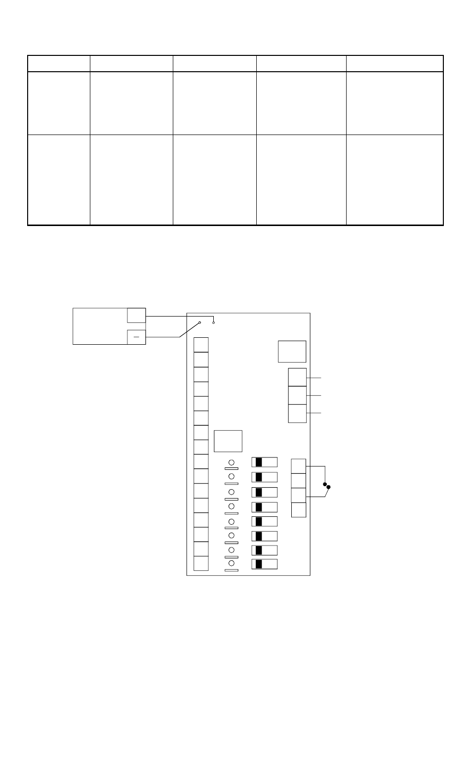
FIG. 2: POWER SUPPLY WIRING WITH CCS-8 BOARD
R2
R1
B+
B-
F1
FA
R8
R7
R6
R5
COMMON NEGATIVE
DC RETURN (0 VOLT)
HO
T
N
EUT
G
RND
11
5 VA
C
I
N
PUT
H
N
G
TERMINALS R1-R8
CLASS 2 TERMINALS P1-P8
SUPPLY +V TO THE TIMER.
EACH TERMINAL IS ON
WHICH IS APPROPRIATE
FOR INSTALLATIONS
WITH MULTIPLE TIMERS
FIRE ALARM
N.C. CONTACTS
OPEN WHEN
ALARM ACTIVE
BATTERY
PACK
(OPTIONAL)
+
A SEPARATE POLYSWITCH
F2
AC
FUSE
H
DC
FUSE
R4
R3
RED
BLACK
ON
OF
F
SLIDE SWITCHES POWER AND DE-POWER EACH
"P" OUTPUT. LED'S SHOW OUTPUT STATUS
P2
P1
P8
P7
P6
P5
P4
P3
3.6 BATTERY CHARGING CAPABILITY
A resistor and diode are present on the CCS board which, together with the power supply,
constitute a battery charging circuit appropriate for standby rated sealed lead acid or gel cell
batteries. Dry cell or NICAD batteries must not be used. Batteries are an option. The
power supply can be used with or without them. The battery pack of the appropriate voltage is
connected to the red and white flying leads following correct polarity. In the event of a line
voltage power failure, the batteries will automatically drive the load at the same DC voltage. If