Replacing the faceplate on the mvp-wds – AMX Wall Docking Station MVP-WDS User Manual
Page 19
MVP-WDS Wall Docking Station & CB-MVPWDS Rough-In Box
13
MVP-WDS Wall Docking Station for MVP Panels
7.
Insert and secure four #4-40 Mounting Screws (not included) into their corresponding holes located
along the sides of the WDS (using a grounded Phillips-head screwdriver) until the WDS is secured
and is flush against the wall.
8.
Follow the steps outlined in the Replacing the Faceplate on the MVP-WDS section on page 13 to
angle the MVP Support Cradle forward and re-install the faceplate.
Replacing the Faceplate on the MVP-WDS
1.
Temporarily apply power to the MVP-WDS by connecting the terminal end of the power cable to
the power supply.
2.
Press the Cradle Activation Pushbutton (located inside the MVP-WDS battery compartment, next to
the battery pins in Battery Slot #2 - see FIG. 5) to angle the Support Cradle forward.
3.
Temporarily remove power from the MVP-WDS to maintain the support cradle at this angle and
keep it from retracting back into the MVP-WDS.
4.
Slide the Faceplate over the angled Support Cradle, toward the Security Release pushbutton’s circuit
board on the MVP-WDS (FIG. 9).
5.
Gently press the faceplate down and under the Security Latch until it rests against the Mounting
Tabs of the MVP-WDS main unit.
Be sure to snap the Faceplate Connectors back into their respective Latches (located along the
bottom rim of the faceplate - see FIG. 7 on page 7).
Verify that the Security Release Pushbutton is properly aligned over it’s LEDs and circuit
board on the MVP-WDS main unit.
Verify that the two faceplate security screw holes on both the Faceplate and the main
MVP-WDS unit are properly aligned.
6.
Insert and secure the two #6-32 Faceplate Security Screws into the top rim of the Faceplate using a
grounded Phillips-head screwdriver.
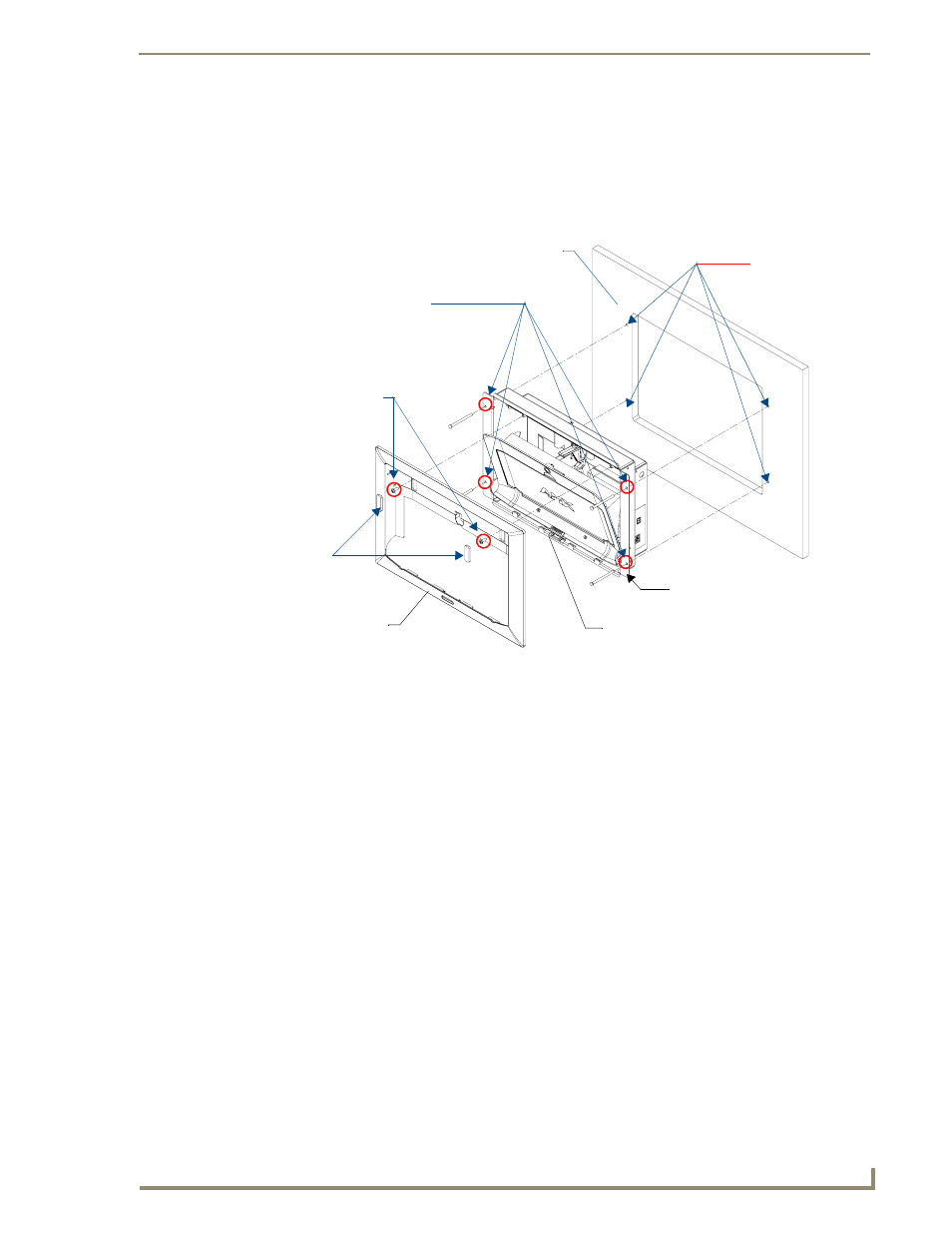
FIG. 14
MVP-WDS installation configuration for solid surfaces
B - MVP-WDS (Main unit)
Attachment is done
Install the four #4-40
mounting screws
A - Faceplate
(bezel)
Faceplate
security
screws (2)
into the four holes
along the edges
of the cutout
Flat surface (can
include a wall, podium, or
other level surface)
(screws not included)
Mounting Tab
Die Cut Foam
covers (2)