AMX Wall Docking Station MVP-WDS User Manual
Page 16
MVP-WDS Wall Docking Station & CB-MVPWDS Rough-In Box
10
MVP-WDS Wall Docking Station for MVP Panels
2.
Thread the USB and Power cables through the surface opening, leaving enough slack in the wiring
to accommodate re-positioning of the unit.
3.
Connect the 2-pin power connector and USB cables to the WDS. The WDS must be installed with
these attached. The USB connectors can be from either a USB extension cable, or a wireless USB
RF transmitter.
4.
Install the four sets of drywall screws and expansion clips into the four oval notch locations along
both sides of the main unit (FIG. 12).
5.
Carefully insert the main unit (with expansion clips) into the cutout so that the Mounting Tabs on
the MVP-WDS lie flush against the wall.
Verify that the terminal end of the power cable is not connected to a power source
before plugging in the 2-pin power connector.
FIG. 11
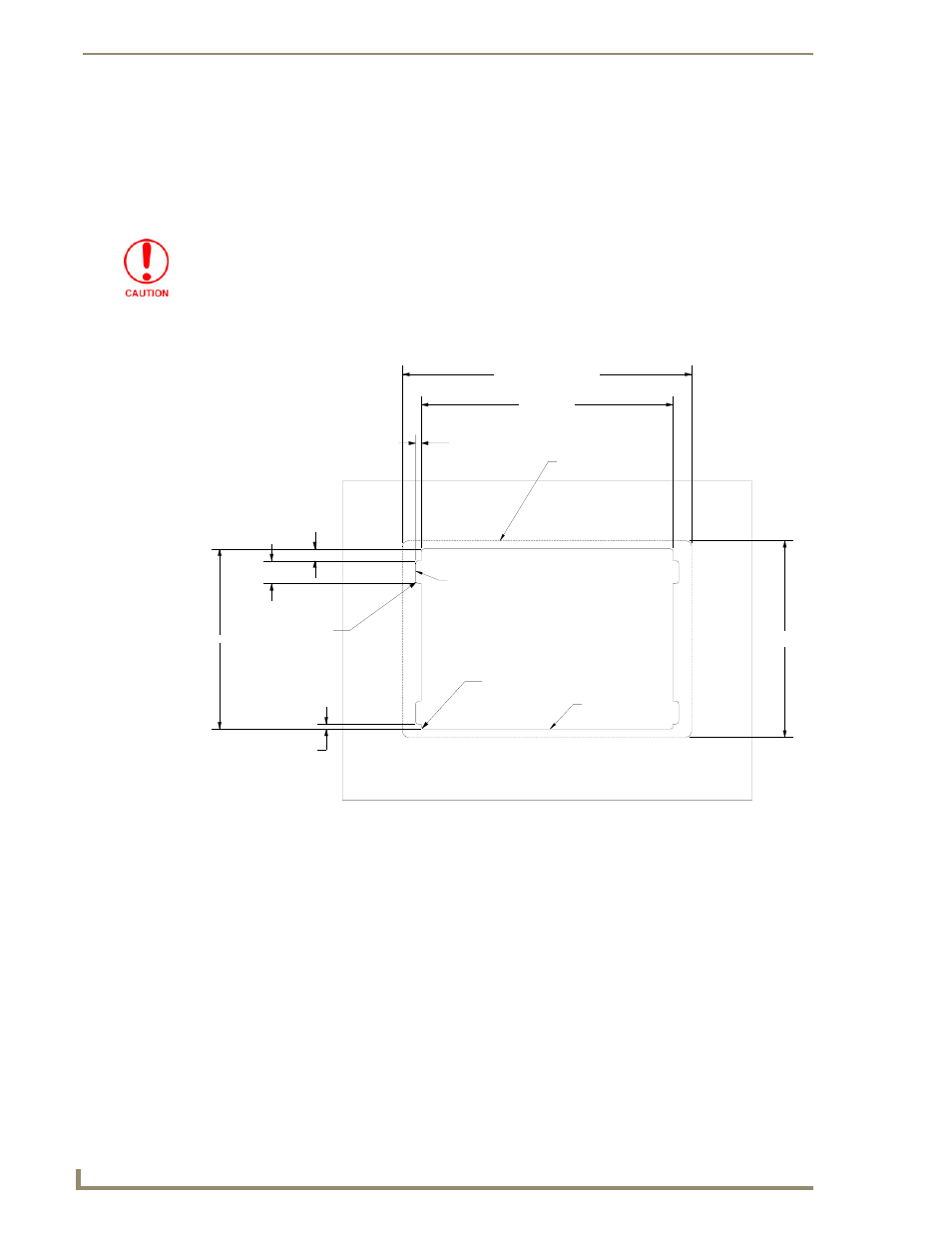
MVP-WDS Wall Mount cutout dimensions using expansion clips
.25 [6MM] TYP
11.06 [281MM]
12.70 [323MM] BEZEL OUTLINE
8.63 [219MM]
BEZEL OUTLINE
2X .52 [13MM]
1.00 [25MM] TYP
7.91 [201MM]
2X .22 [5MM]
FRONT BEZEL OUTLINE
CUTOUT
4X R.13 [3MM] MAX RADIUS IN CORNERS
R.13 [3MM] TYP
THESE NOTCHES ARE ONLY NEEDED IF UNIT IS INSTALLED USING
DRYWALL EXPANSION CLIPS (4 PROVIDED)