Rivers edge® spin shot – Rivers Edge RE637 Spin Shot User Manual
Page 8
Check for parts online at
www.HuntRiversEdge.com or call 800-450-EDGE (3343) M-F 8-5
8
Operator's Manual
Rivers Edge® Spin Shot™
17. The remaining (2) ladder sections are assembled to the top ladder
assembly on the ground in the following order: bottom section (SL51
ladder); second section (SL52 ladder); third section (SL78 ladder);
top section (assembled top, platform section). SEE FINISHED SPIN
SHOT LADDER.
18. With all sections assembled together on ground, secure all sections
together using (4) provided spring lock pins. Handle of spring lock
pin must be put to the outside of ladder side rails. SEE FIGURE 10
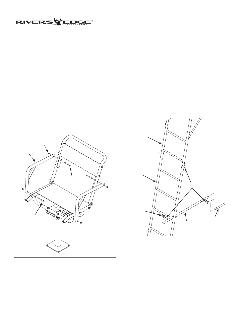
19. a. Attach the stabilizer bar extension tube (48053) to the second
ladder section mounting bracket using (1) provided spring lock pin.
SEE FIGURE 10
b. Slide the stabilizer bar (48052) into the extension tube and attach
the two pieces together using (1) provided spring lock pin. Spring
lock pin must go through both the extension tube and stabilizer
bar at appropriate hole to achieve desired distance from tree.
Adjustment in length may be needed when ladder is uprighted later
in instructions. SEE FIGURE 10
15. Attach the (2) armrests (17635) to the seat frame and backrest
rim using (4) provided 1/4-20 x 2-1/4” bolts, locknuts and steel
washers. SEE FIGURE 9. You must now tighten all nut and
bolt combinations securely; DO NOT CRUSH TUBING WHEN
TIGHTENING!
NOTE: The armrests are more than 3” longer on one side. Bolt the
longer side to the backrest and the shorter side to the seat frame
to achieve proper backrest angle.
16. a. Attach the (2) provided 9” armrest pads (200304) to the armrests
and the 128” shooting rail pad to shooting rail by wrapping around
metal tubing and attaching Velcro together.
b. Using a rubber mallet, tap in (2) plastic pipe plugs (48869) into
each end of shooting rail.
c. Attach the camo curtain (48086) to the shooting rail/platform
by wrapping top edge around padded shooting rail and attaching
Velcro together. Zippered door should be aligned with the ladder.
Pull bottom edge with sewn-in elastic down to platform and secure
Velcro straps around platform frame.
FIGURE 9
armrest
1/4-20 x 2-1/4"
bolt
locknut
1/4-20 x 2-1/4"
bolt
third ladder
section
second ladder
section
mounting
bracket
extension tube
spring lock pins
stabilizer bar
FIGURE 10