Relay contact outputs, Low voltage cable, 9060 cascade low voltage controller - installation – Ransburg 9060 LV Cascade Controller 80131-XXX User Manual
Page 24: Maximum contact ratings
9060 Cascade Low Voltage Controller - Installation
19
CP-13-07.2
Some codes may require the interlock
wiring to be run in conduit. In this case,
shielded cable is not necessary, but the
conductors used should still meet the rat-
ing specified above.
N O T E
and 105°C and its conductors should be
0.8mm
2
(18 AWG) minimum. Secure the
cable to the interlock connector as de-
scribed in “I/O Connections” in the
“Installation” section of this manual so that
the shield of the cable is connected to the
chassis of the enclosure.
5. Replace the top cover, secure the screws,
replace the fuses, and reconnect the AC
source.
The interlock contacts (supplied by us-
er) should be rated for at least 1 amp at
240 VAC.
N O T E
Description
DC
AC
Max. Switching Capacity
60W
62.5VA
Max. Operating Voltage
125VDC 125VAC
Max. Operating Current
2A
2A
MAXIMUM CONTACT RATINGS
The Controller MUST be OFF when the
applicator is removed or reinstalled.
!
W A R N I N G
RELAY CONTACT
OUTPUTS
A set of relay contacts for high voltage (CR1)
and fault (CR2) conditions is provided at 2TB-2
and 2TB-4 (See Figure 8). One end of these
relay contacts are connected together and also
connected to a source input terminal 2TB-3
(See Figure 11). When a source voltage is
present at 2TB-1 and either the high voltage is
on or a fault condition occurs, the source
voltage will become available at the output end
of the corresponding contact. Maximum
contact ratings are as follows:
When wiring to 2TB, use a shielded cable and
route the wiring through the standard I/O
connector as described in the “I/O Connectors”
section of this manual.
An internal 24 VDC source voltage is
available at 2TB-1. Using a jumper wire,
this voltage may be connected to 2TB-3
to be used as the source voltage for the
relay contact outputs. In this case, the
total current sourced should not exceed 1
amp.
N O T E
The total resistance of the series inter-
locks between L2 and L3 should be less
than 300 Ω.
N O T E
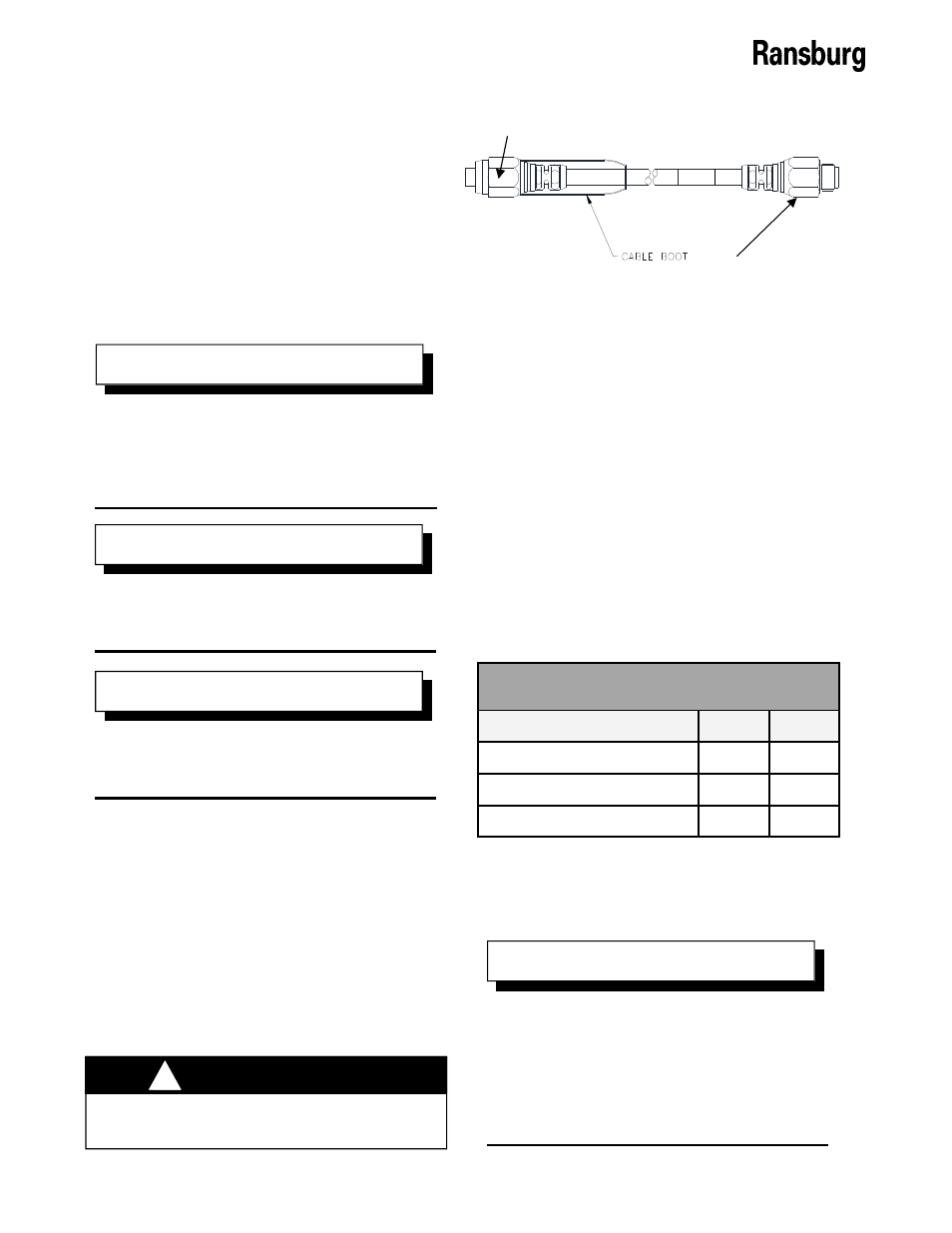
LOW VOLTAGE CABLE
Insert the connection control unit end of the
low voltage cable into the controller. Make
sure that the male notch on the low voltage
cable lines up with the female notch on the
controller, push in (by hand) as far as it will go,
then tighten the nut. Use the same procedure
to connect the low voltage cable to an external
cascade unit. Refer to Figure 12.
Connection-Cascade End
Connection-Control Unit End
Figure 12: Low Voltage Cable