Connection interface, Connectors, 9060 cascade low voltage controller - introduction – Ransburg 9060 LV Cascade Controller 80131-XXX User Manual
Page 16
9060 Cascade Low Voltage Controller - Introduction
11
CP-13-07.2
Left (-)/Right (+) Buttons
The left(-)/right(+) buttons in the normal operat-
ing mode are used to modify, decrease and
increase respectively, the currently selected
preset value. If the button is pressed and
released, the preset value is changed by 1 kV
at a time. If the button is held for over a 1/2
second, the value will begin changing by 5 kV
increments.
Reset Button
The reset button is used in the normal operating
mode to clear fault or overload conditions. This
will NOT prevent any other active fault condi-
tions from triggering a new fault.
HV Control Button
This button, shown in the center of Figure 3, is
not functional for handgun units.
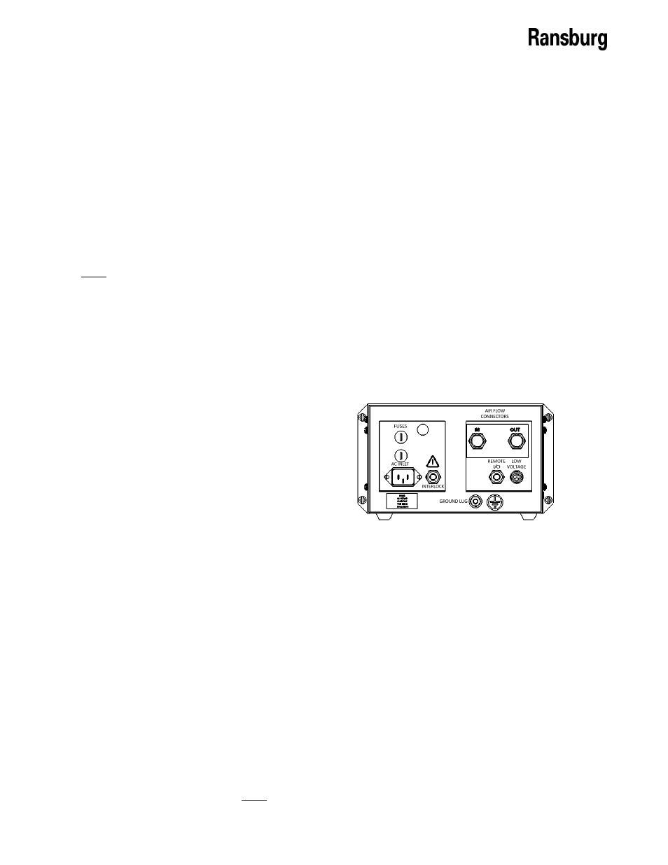
CONNECTION INTERFACE
The 9060 Controller connection interface shown
in Figure 4, provides all of the required connec-
tions for setting up a local controlled painting
system. This connection interface consists of
one (1) low voltage cable connector, one (1)
standard I/O connector, one (1) interlock I/O
connector, one (1) ground lug connection, one
(1) air flow switch connection, two (2) fuses,
and one (1) AC inlet receptacle.
CONNECTORS
Low Voltage Cable Connector
The low voltage cable connector is located on
the far lower right of the connection interface.
This connector is designed for use with stand-
ard low voltage cable 76298. The low voltage
cable connects the 9060 controller to the
external cascade .
Standard I/O Connector
The standard I/O connector is located just left of
the high voltage cable connector. This connect-
or is provided as the entry point for a shielded
multi-conductor cable used for remote I/O
signals and includes the required cable grom-
met hardware to keep the cable in place with
minimal strain. This connector is NOT used for
handgun units.
Interlock I/O Connector
The interlock I/O connector is located just to the
right of the AC inlet receptacle. This connector
is provided as the entry point for interlock signal
wiring for the booth fan, conveyor, and solvent
supply. The connector includes the required
cable grommet hardware to keep wiring in place
with minimal strain. For more information on
the interlock connections, please see the
“Installation” section of the service manual.
Ground Lug Connection
The ground lug connection is located below the
standard I/O and has a ground logo sticker to
the right of it. This lug is provided as an exter-
nal ground connection point used to ground the
9060 to an earth ground via a ground cable.
This ground lug connection can also be used as
the ground point for the high voltage cable
ground.
Air Flow Switch Connection
The air flow switch connection is installed to
provide a pneumatic trigger signal for handguns
indicating that the trigger has been actuated.
This signal is used to turn on the High Voltage
output. Both threaded connectors of the air
flow switch will come covered with red protect-
ed caps.
AC Inlet Receptacle
The AC inlet receptacle is a standard IEC C14
Appliance Inlet connector with a maximum
rating of 250 VAC. It can handle both 110VAC
and 240 VAC inputs at 50 or 60 Hz. The unit is
shipped with the appropriate rated AC cord for
the particular installation.
Figure 4: 9060 Connection Interface